
Activating SOLIDWORKS SimulationXpress
SOLIDWORKS SimulationXpress is a basic finite element analysis (FEA) simulation tool enabling you to run basic linear static analyses of single bodied parts. SimulationXpress is included with every SOLIDWORKS Standard and Professional software package.
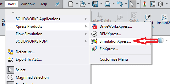
It can be found on the menu bar under; “Tools”, as seen here:
Although the tool is included within the install, it still needs to be activated. The first time it is loaded, the following screen appears:
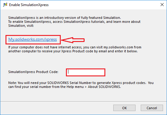
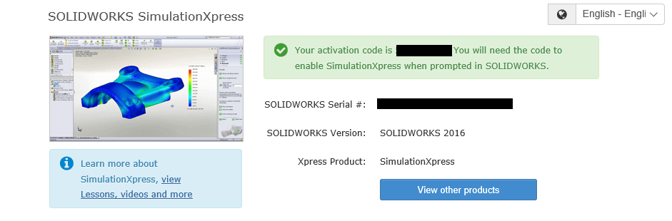
In order to activate the tool you need to select the link provided, which takes you to the SOLIDWORKS website, and as soon as you log into your customer portal account, a code is generated as seen in image 3. This then needs to be inserted into the window below the link on the activation window as seen in image 2. You are then able to begin your study!
Using SimulationXpress
Now that the product has been activated, the SimulationXpress wizard appears within the task pane on the right hand side of the interface. The wizard helps walk the user through setting up and running the study step by step, so even if you are unfamiliar with the process of running a FEA study, the fundamentals are explained thoroughly. This is a great tool for the beginner!
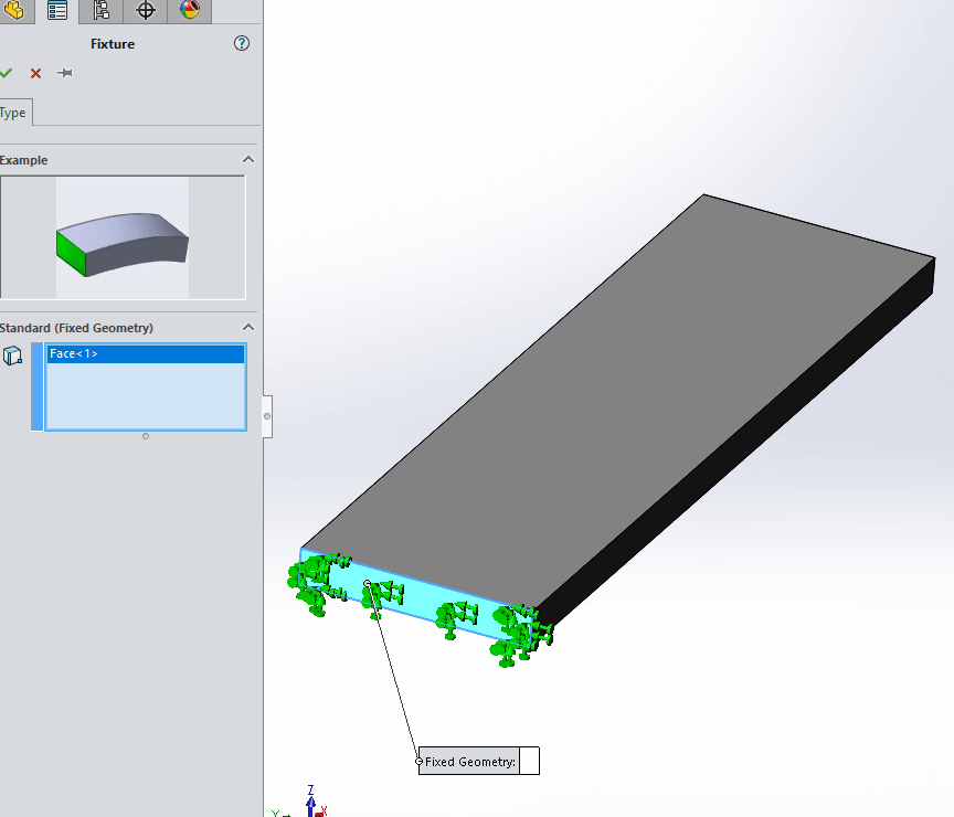
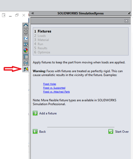
1: Fixtures
The first step to running your analysis is to select where on your model you would like to fix the geometry. This is necessary as no fixtures would result in the model “floating off into space” as Newton’s third law of motion states that each force must have an equal and opposite reaction force. At least one selection must be made. As seen in Image 4, one face has been selected. The face is then populated with green arrows explaining all 6 DOF have been removed, thus fixing the geometry.
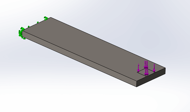
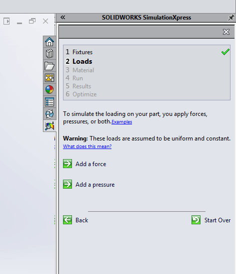
2: Loads
The next step is to apply a force or pressure to a particular area on the model. In both cases, a face is the only selection available. (Tip: Use the split tool command in order to specify the exact area the load is being applied to). This face is then populated with purple arrows displaying the area and direction of the load being applied.
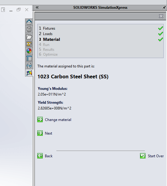
3: Material
In order for the study to calculate accurate stress and displacement results it requires the material properties, such as the elastic modulus and yield strength. Therefore a material must be applied to the part/body for the study to continue. Note that running a study within SimulationXpress allows for linear static analysis only. So non-linear (plastic) deformation is not taken into account.
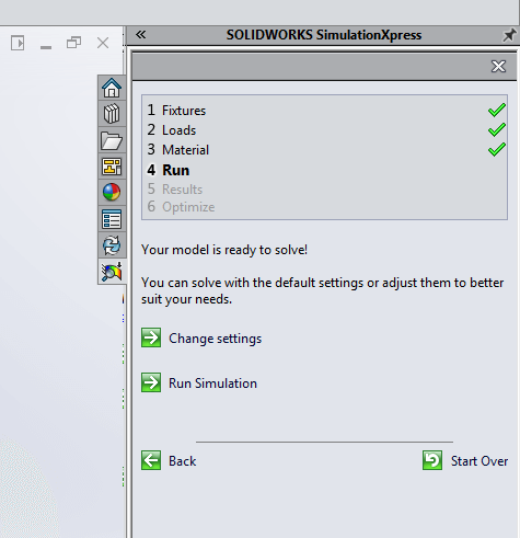
4: Run
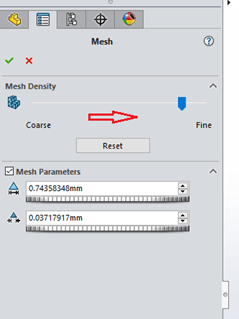
Before you run the study you have the ability to change the mesh settings. This affects the accuracy of the results, so the finer the mesh, the higher the accuracy of results, but the time taken to solve is longer. Once you have chosen this you are now ready to run the study!
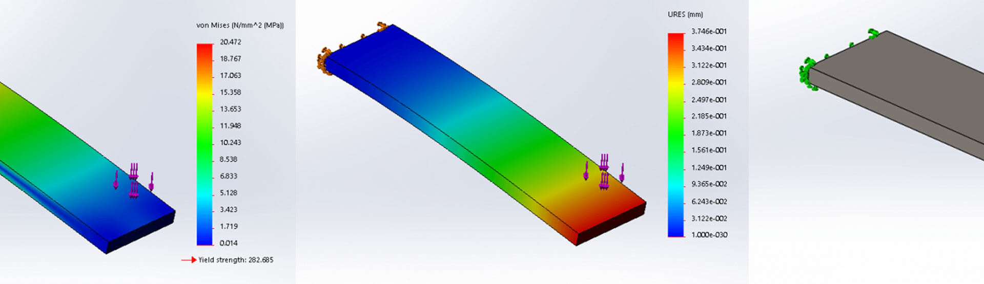
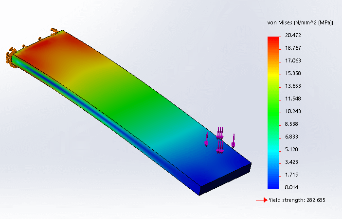
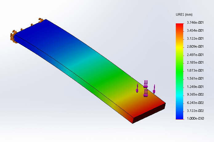
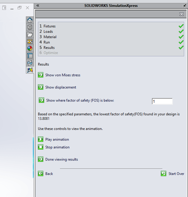
5: Results
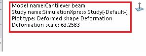
Once the study has been solved, the displacement of the geometry is automatically animated. Note that the deformation is usually largely scaled up in order to display the results clearly. This scale can be seen and edited within the top left of the graphics window.
You also have two options; to continue, or to go back and edit the study parameters. By choosing to continue, you are then able to view the stress, displacement and factor of safety of the studied geometry as seen below.
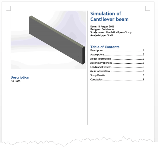
Once you have reviewed the results, you can then automatically generate a report of the study using Microsoft Word, or alternatively you can export the file to eDrawings, enabling a user without SOLIDWORKS to open and review the results of the study in 3D.
This is a great tool in terms of calculating the load impacts on a design and in general evaluating the performance of your model, eliminating the need for so many prototypes etc. If studies on more advanced geometry are required, further Simulation packages are available. SOLIDWORKS premium enables you to perform a study on an assembly, for example.
Please note that all simulation results are approximate and need to be verified by real life results. The full package of SOLIDWORKS Simulation Professional and Premium provides significantly more detail, flexibility and therefore accuracy.
We hope you found that useful!
Have you seen our blog archive where we have posted plenty of helpful articles? We also have a fantastic video library filled with easy-to-follow videos on a number of topics inspired by other SOLIDWORKS users – take a look.
Also, don’t forget to follow us on twitter for daily bite size SOLIDWORKS tips, tricks and videos.


