

SOLIDWORKS Electrical comes pre-loaded with a large library of user-selectable symbols. Even so, there may be occasions where it is necessary to create your own. Here’s how you do it…
Step 1
Go to the ‘Library’ tab in SOLIDWORKS Electrical and select the ‘Symbols manager’ command
The Symbols manager will open in its own dialogue box.
Step 2
Select ‘New’
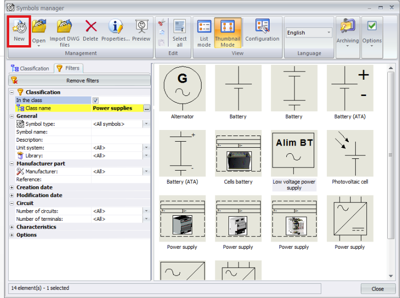
This will allow you to create a brand new symbol. Please note you could also copy and edit an existing one.
Step 3
Enter the relevant details into the ‘Symbol properties’ dialogue box:
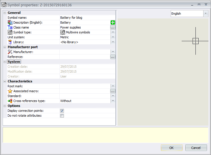
We’re creating a battery in the above example – Below are the fields we have edited.
‘Symbol name’
‘Description’: A description of what the symbol is. You could have 2 different battery symbols which have the same description. The symbol name must be unique.
‘Class Name’: What classification do you want the symbol to go into? The relevance of this will be seen when searching for symbols and the default mark they take, default 2D footprint, etc.
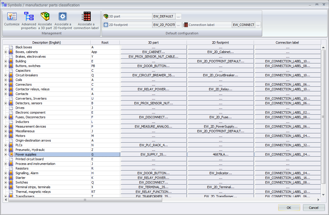
So in the above example, if we place the symbol in ‘Power supplies’, when we use that symbol in a drawing the default mark will be ‘G’.
‘Symbol Type’: You will need to choose whether this symbol is to be used in a 2d schematic, line diagram, 2D Cabinet layout, etc.
‘Unit System’: you will need to correctly define your unit system, or the symbol maybe scaled incorrectly.
You can also see within the properties that it is possible to define a default manufacturer part, root mark. In this example I will leave those options blank.
Step 4
Press ‘OK’ and open the symbol.
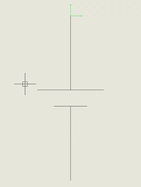
Locate the symbol and open it in its own window. You will be presented with an empty drawing. You should be able to see the origin (X:0, Y:0). We can use this as default insertion point for your symbol.
Step 5
Create the symbol using the drawing tools in SOLIDWORKS Electrical.
Using co-ordinates, snaps, grids and orthographic mode is key when creating symbols. If you do things “by eye” there is a very good chance your symbol will not align itself to your wires.
In the below example, we drew 4 lines with these X,Y Co-ordinates:
Line 1: Start: 0,0 / End: 0.-2.25
Line 2: Start: 0,-2.75 / End: 0,-5
Line 3: Start: -1,-2.25 / End: 1,-2.25
Line 4: Start: -0.5,-2.75 / End: 0.5,2.75
Step 6
Add attributes.
When the symbol is placed, you will want it display attributes and will almost certainly want to display the component mark and manufacturer data as well.
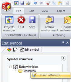
In the right pane you will see an attributes folder – Right click the folder and select ‘Insert attribute’:
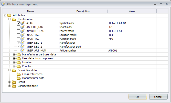
In this example, we decided to add Component mark, Manufacturer & Manufacturer part:

Step 7
Add a new circuit:
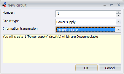
You will need to specify how many circuits you wish to add, the circuit type and the information transmission.
The information transmission can be set to ‘Disconnectable’, ‘Passing’, ‘Hyper passing’ and ‘Hyper hyper passing’ (a discussion for another blog!) – We set it to ‘disconnectable’.
Step 8
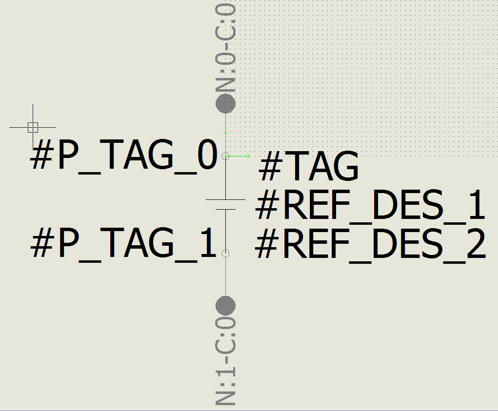
Insert Connection points for the circuit
Once the circuits have been established, connection points for those circuits must be added. The connection points can be rotated to the correct orientation by right clicking.
Step 9
Close and save the circuit.
Success!
The symbol is now ready for use, here’s how it looks in a schematic diagram with a manufacturer part associated to it:

We hope you found that useful!
Have you seen our blog archive where we have posted plenty of helpful articles? We also have a fantastic video library filled with easy-to-follow videos on a number of topics inspired by other SOLIDWORKS users – take a look.
Also, don’t forget to follow us on twitter for daily bite size SOLIDWORKS tips, tricks and videos.


