
The functionality within SOLIDWORKS Plastics allows a user to create a runner system specific to the needs of their design. Once a runner system has been decided on, an analysis can be run on it to ensure that it is adequately balanced, meaning multiple injection moulded parts can be created within the same cycle, and from the same runner system. Ensuring a consistent quality of fill across two separately shaped designs.
This blog post details how to design a runner system in SOLIDWORKS and also how to perform a runner balancing study.
Preparing your model
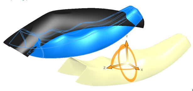
To begin, you will need a part model which has the two halves of your design inserted into it. The ‘Move/Copy Body’ feature can be used in order to move one half of the design to a new location (Insert>Features>Move/Copy Body).
The designs will need to be moved to a relative position, as if they are sitting in a mould. In the picture example below, the ‘Move/Copy’ feature has been used twice; once to rotate, once to translate the model.
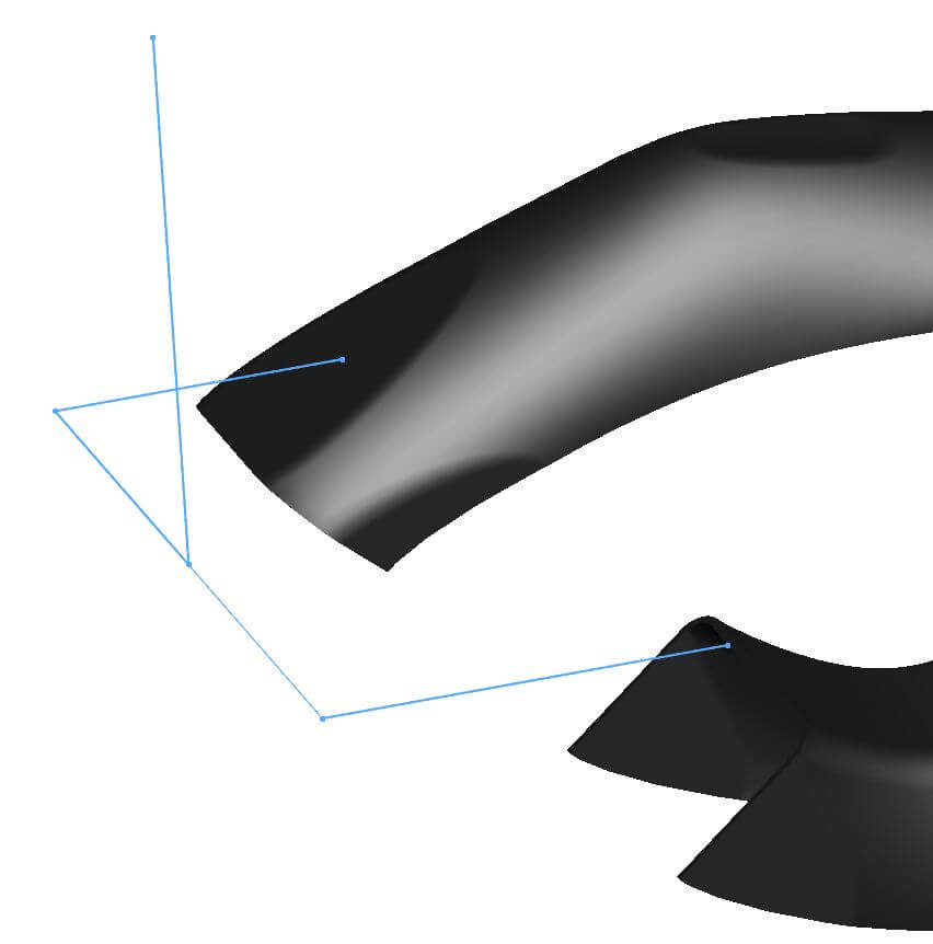
Once the parts are positioned a simple line sketch will need to be drawn to represent the runner system. The ends of each line are coincident with the edges of the model. The example shown in the picture is made up of multiple sketches. A combination of 2D sketches, or a 3D sketches can be used if preferred. After following the above steps, the model will be ready for a plastics analysis.
Setting up the Plastics Study
SOLIDWORKS plastics needs to be turned on to do a runner balancing study. This can be done from the Tools>Add-ins menu. It is worth noting that in order do runner balancing within SOLIDWORKS plastics, you will require a Plastics Professional or Plastics Premium licence.

A mesh can be created within the property manager for SOLIDWORKS Plastics. The example shown in this exercise uses a shell mesh, because the model has a thin walls with a constant wall thickness. Right clicking on the shell mesh icon in the plastics property manager will allow a manual mesh to be inserted – giving you more control over things like triangle size.
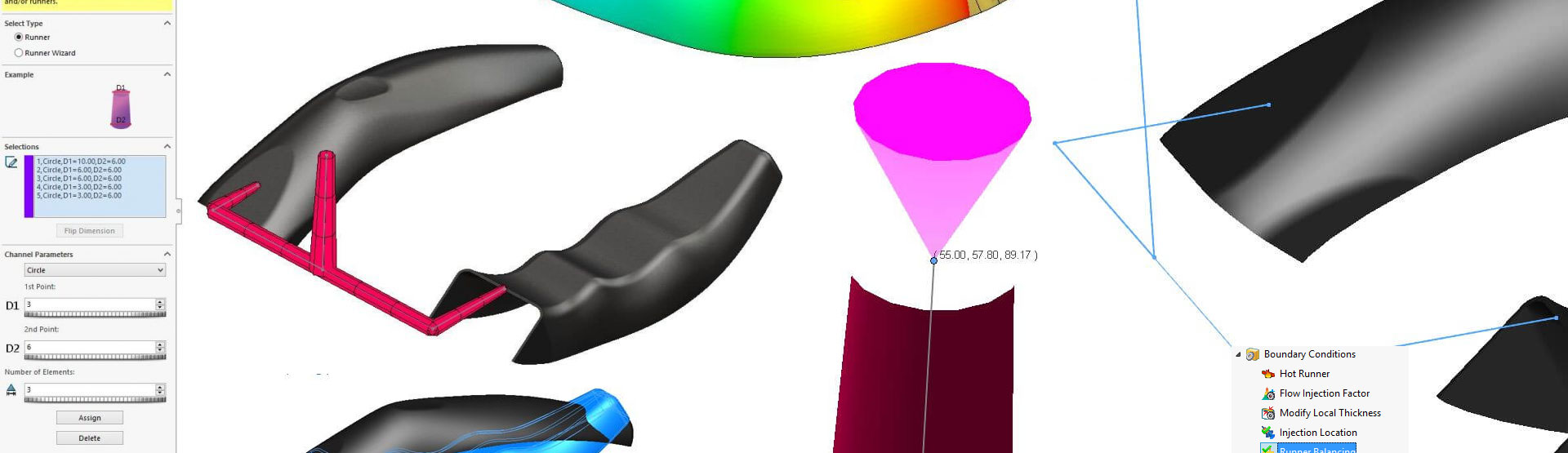
Right clicking on the runner design option under the mesh node in the properties manager will bring up the runner design tool. From here the runner system can be created around the sketches created earlier.
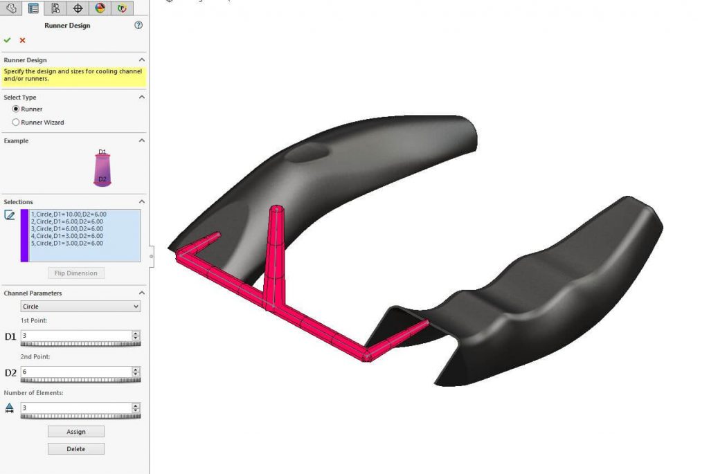
To use this tool, select a sketch line from the graphics area, set the dimensions on the left (D1 & D2) and click ‘Assign’ to set the values onto the selected line. If the values assign themselves the wrong way round, select the line from the ‘Selections’ box and click ‘Flip Dimension’. Don’t worry too much about the exact size of the runner system, as the runner system will be balanced soon. Do this same process for each line and, once complete, hit the tick.
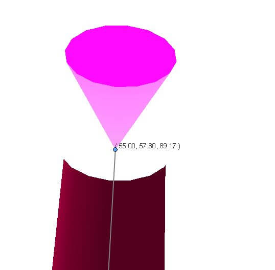
An injection location needs to be set next. Right click on this option in the property manager. To set this onto the end of the runner system, click on the end point and select add location, you can then accept this menu.
The material will also need to be set in order to accurately run the plastics flow simulation. This can be done from the polymer option under materials. By right clicking the material can be set by opening the database.
Running the simulation
It is a good idea to run an initial Plastics Flow Simulation post simulation set up to ensure things like injection pressure and mould temperature are accurate (right click on ‘Flow’ in the property manager to do this). If there is a problem with your runner design, one half of the model will fill before the other. You may be left with a Short Shot on one half of the design.
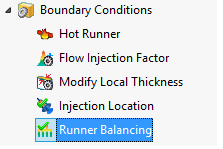
To fix this issue, right click on ‘Runner Balancing’. The settings for this can now be opened. Once opened, the setting inside the property manager can be adjusted to control things like the number of iterations. To run the simulation click ‘Calculate’.
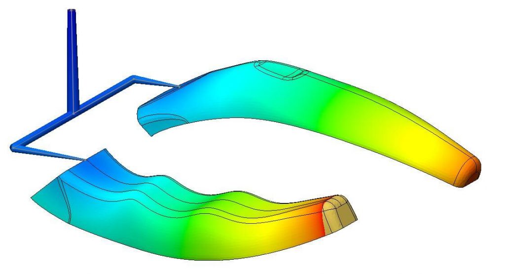
The simulation can take in excess of an hour. Once complete, you will be presented with your runner system in a balanced state. If re-run, the Plastics Flow Simulation will complete equally on both sides.
We hope you found that useful!
Have you seen our blog archive where we have posted plenty of helpful articles? We also have a fantastic video library filled with easy-to-follow videos on a number of topics inspired by other SOLIDWORKS users – take a look.
Also, don’t forget to follow us on twitter for daily bite size SOLIDWORKS tips, tricks and videos.


