
[Video Transcript]
As a designer, you’ve always required the most powerful (which usually means the most expensive) workstations. But with more people working remotely than ever before, you need a more flexible environment. With the 3DEXPERIENCE® Works Platform, you can design on the cloud using any device without sacrificing the performance and power you need to stay productive no matter where you are.
In this demonstration, you’ll see an entire design process on multiple components of a circular saw from concept to manufacturing, entirely within a web browser.
3DEXPERIENCE® Works cloud-based design apps for Industrial Design
Dan’s our industrial designer in charge of ergonomics and aesthetics. Dan’s a mechanical engineer who will prepare the models for manufacturing. Let’s drop in on Dan as he shapes a grip handle with 3D Sculptor.
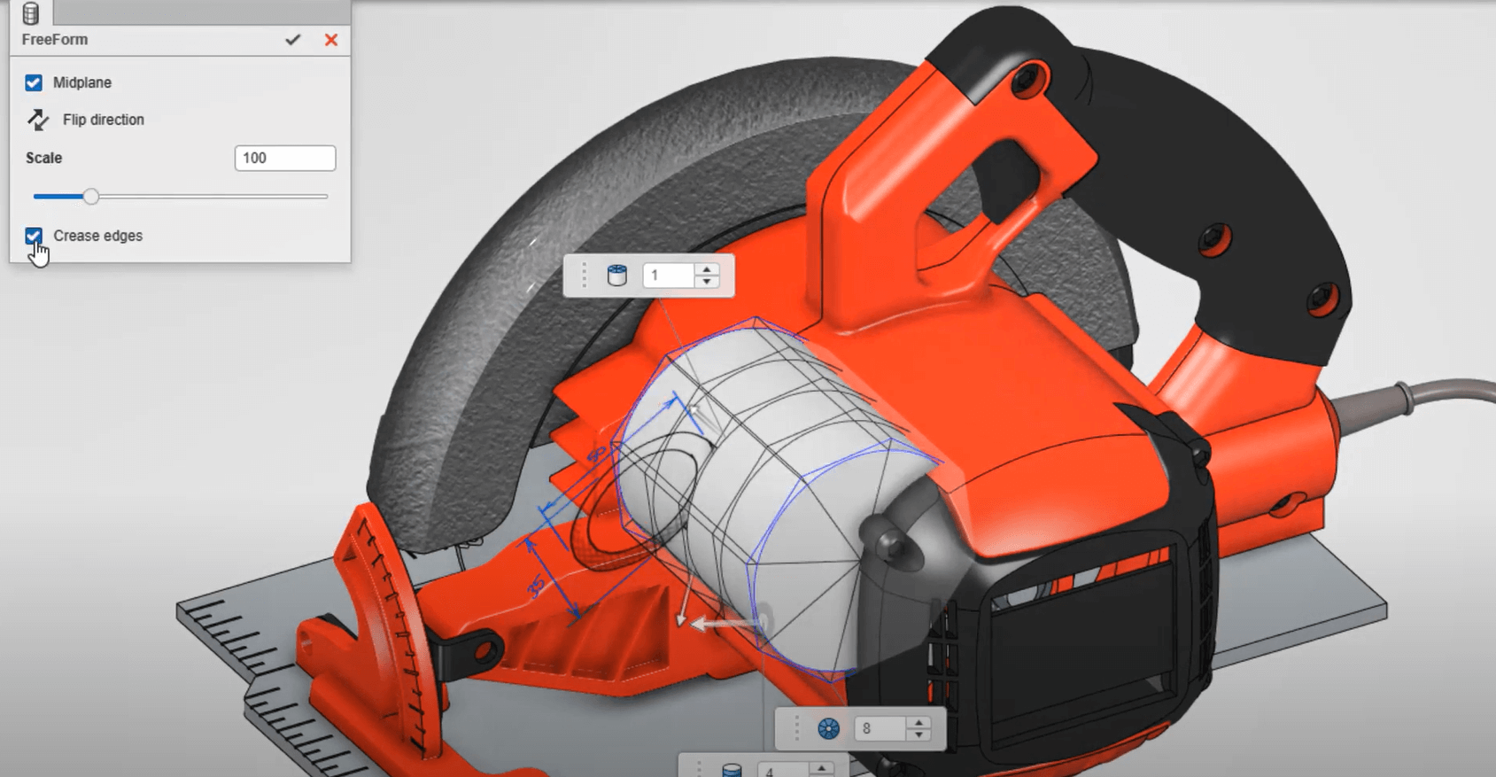
Getting started is easy, Dan picks a cylinder and drops it directly on the origin. Since flat faces will be incorporated into this design, he can get a head start by checking the ‘Crease Edges’ option while placing his initial shape.
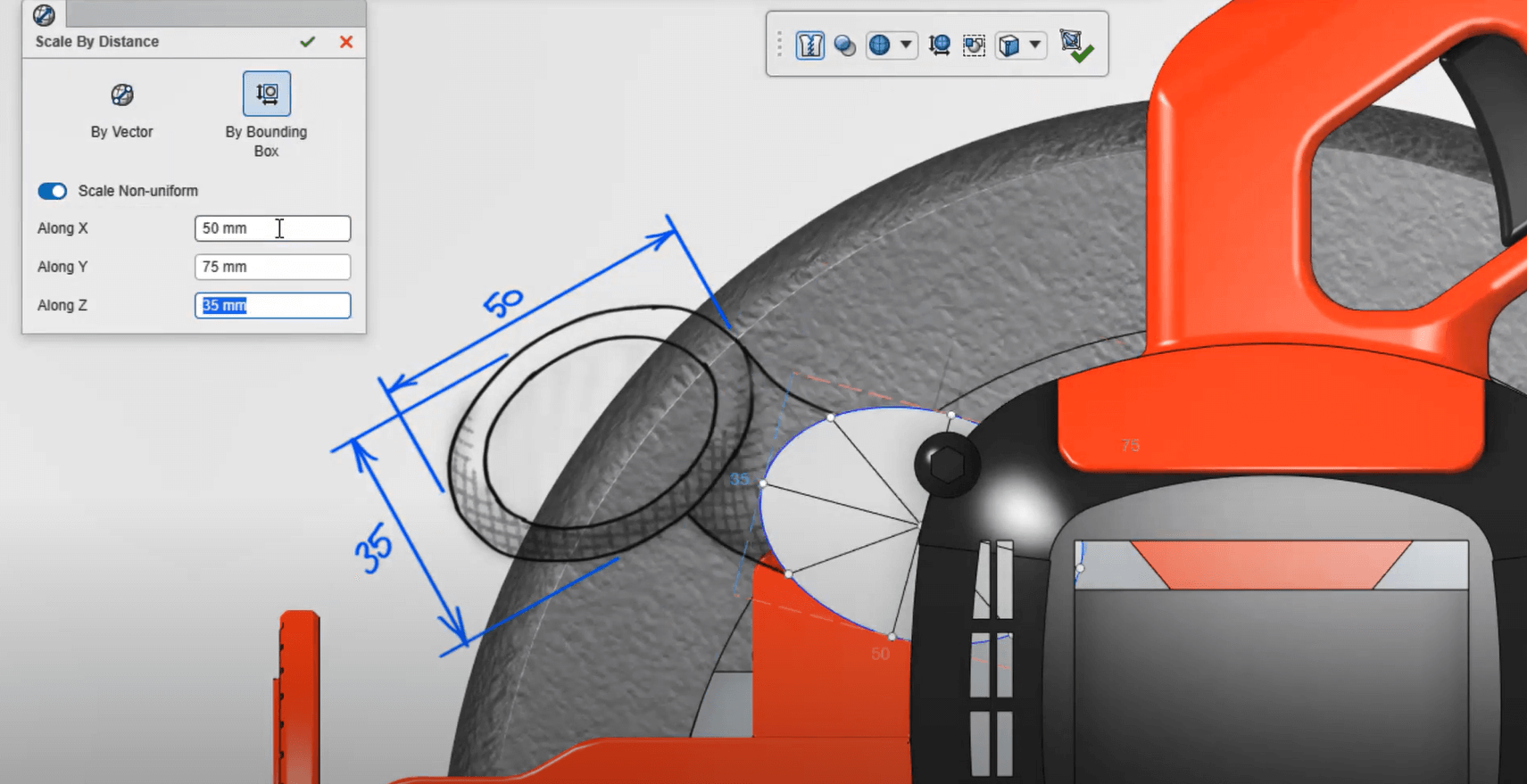
With 3D Sculptor, Dan can freely push and pull the model into any shape imaginable, but, most of the time designs are required to fit within a specific boundary. ‘Scale by Distance’ applies a parametrically-driven ‘Bounding Box’ where he enters a series of dimensions, and the shape snaps precisely to size. Using the Ctrl+A keyboard shortcut, all vertices are selected at once. This makes translating an entire shape to a new position a breeze.
To maintain a uniform aspect ratio while scaling this side face, Dan can hold the Alt key while dragging any of the scaling dots on the robot manipulator. This shortcut will generally scale in all three dimensions, but since this face was planar, it conveniently maintains its flatness.
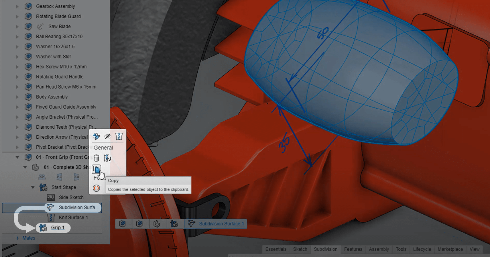
Opening the door to many creative workflows, multiple sets of features can be created within a single Physical Product. In this case, Dan would like to propose various concepts of this grip, by creating a new feature set for each of his concepts. He can simply copy and paste features from one set into another. Each feature set can have unique colour properties and display states. And by double-clicking the copied Subdivision feature, Dan can get started on his first concept of the grip while leaving the original start shape intact.
By utilising the Alt+Drag scaling technique, Dan can wrap up this concept in no time. As views change, the area of focus stays cantered on the screen. This allows Dan to check his edits from multiple angles without having to continually wrestle with zooming and panning.
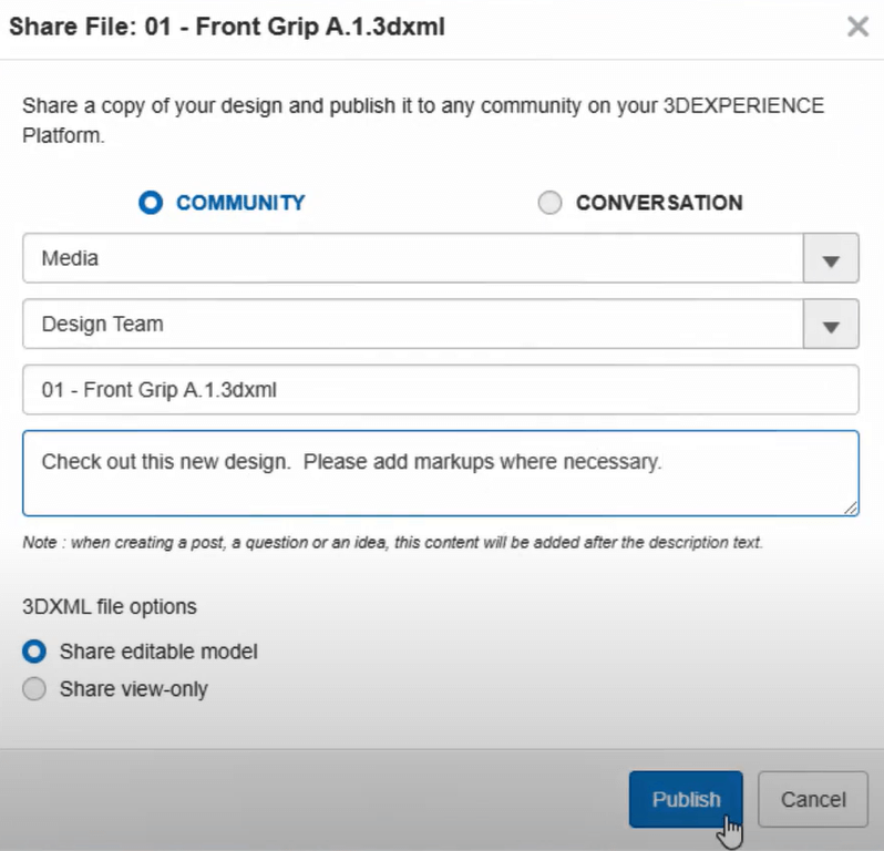
Finally, to collect feedback from the rest of his team, Dan can post the entire 3D model to a community directly from the design app. This streamlines the communication process allowing teams to arrive at the perfect design faster than ever. With the ability to create sub-divisional models directly in a browser on any device, complex shapes have never been easier to create.
3DEXPERIENCE® Works cloud-based design apps for Mechanical Design
After starting the design in 3D Sculptor to create the ergonomic grip handle, it’s now been turned over to Don, the Mechanical Engineer, to complete the design and prepare it for manufacturing with 3D Creator.
Don will need to create the stem connecting the body of the circular saw to the grip handle. To start, Don can create a mounting flange with little effort. By preselecting a face in context of the assembly, he can skip the sketch and extrude his first feature. Sketched ellipses include construction lines making them easy to orient.
For example, Don can snap the quadrants of the ellipse to the midpoints of external model edges, or he can also click on both the point and the edge, opting to create the same relationship in the pop-up menu. These relations will fully define the sketch.
While extruding the feature, a preview is displayed making it easy to confirm the correct end condition has been applied.
But on second thoughts, Don is underwhelmed with the resulting shape, and would prefer a sleeker look. To accomplish this, he can roll the design back before the Extrude feature to create a curved path.
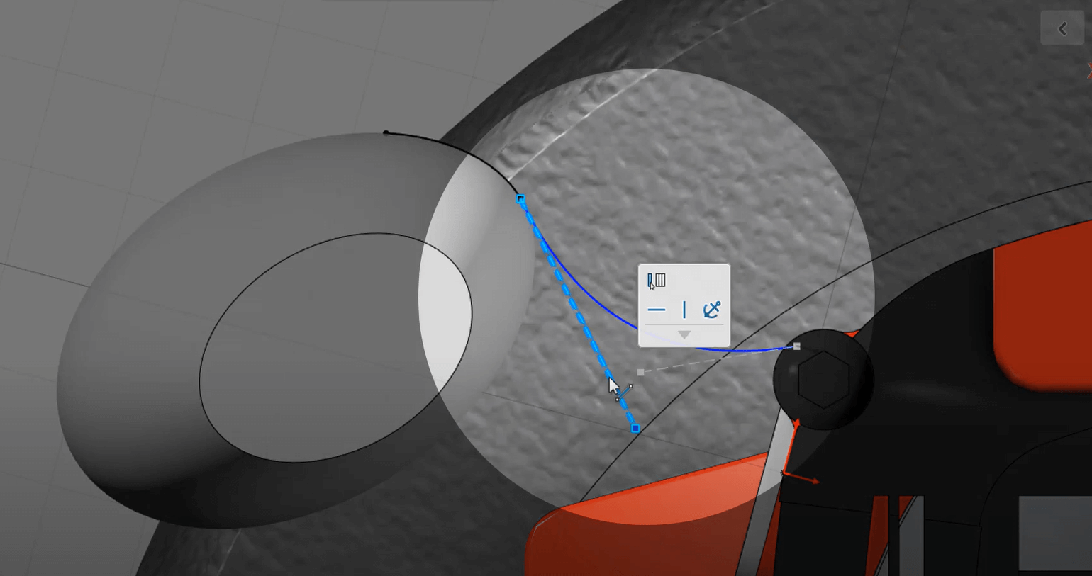
Starting with a two-point spline, he can activate the spline handles to achieve full control over the curvature. Relationships can be applied to both ends of the spline, and the handles can be adjusted until it looks just right.
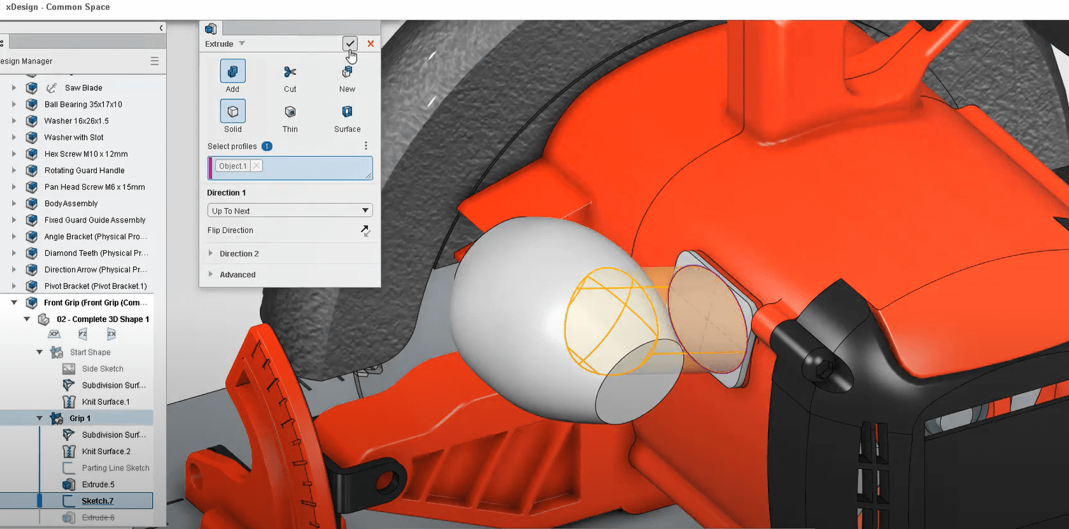
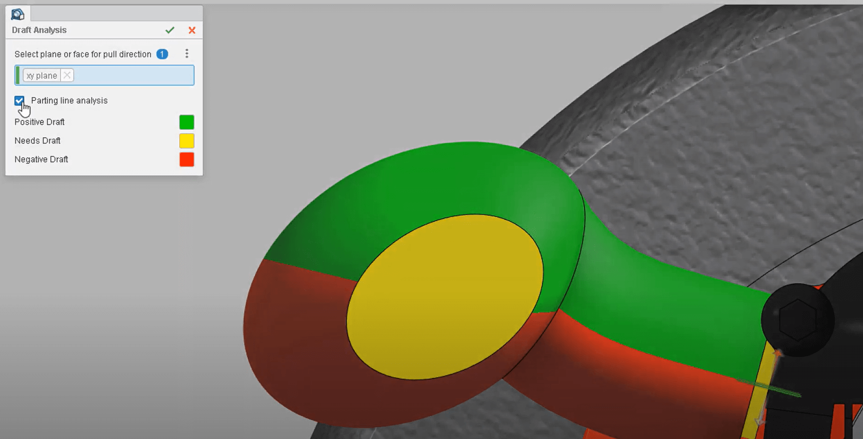
Don rolls the model forward to edit the original Extrude feature. Not only can an Extrude feature be changed to an Extrude Cut, it can even be transformed into a Revolve or ,in this case, a Sweep. It’s called a ‘Super Feature’ and it provides an unprecedented level of flexibility as all references are maintained. Since this part will be injection moulded, it’s important to specify a parting line. By activating the ‘Parting Line’ option on the Draft Analysis tool, Don can pinpoint its exact location.
After adding a few more features, Don has split the body into two halves. To make these bodies easier to work with, they can be divided into separate sets of features. This way, each set of features will be independent from each other. By hiding the other feature sets, Don can focus on the lower half of his design.
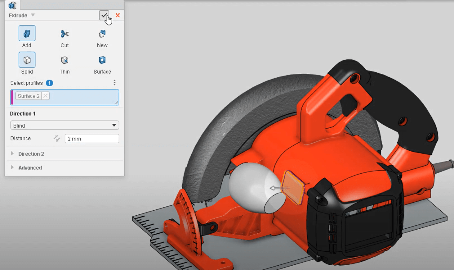
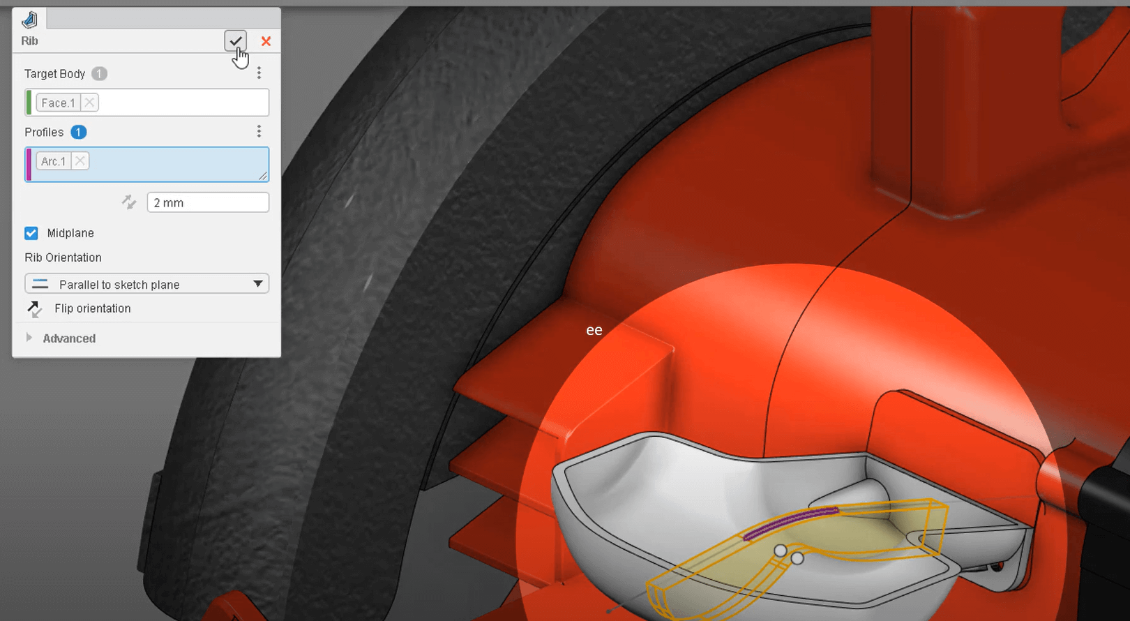
To lighten the design and prepare it for molding, Don adds a 2mm Shell feature. To reinforce the hollowed design, he can sketch a profile for a Rib. Even without perfectly trimming/extending the sketch entities, the Rib feature will project the geometry to fill the internal volume of the component. If necessary, Draft could be added at the neutral plane or where it intersects the inside walls of the part.
Thanks to the flexible design workflows, design changes are nothing to be afraid of in 3D Creator. And with the visual insight provided within modes like Draft Analysis, Don can rest assured this part is ready to be sent to manufacturing. Having the right tools allows you to get to market faster and reduce costs. For example, the milled angle bracket and the base plate of this circular saw is not only expensive to manufacture but also require additional assembly steps. Don recognises this, so he decides to use 3D SheetMetal Creator to consolidate these two components into one.
3DEXPERIENCE® Works cloud-based design apps for Sheet Metal
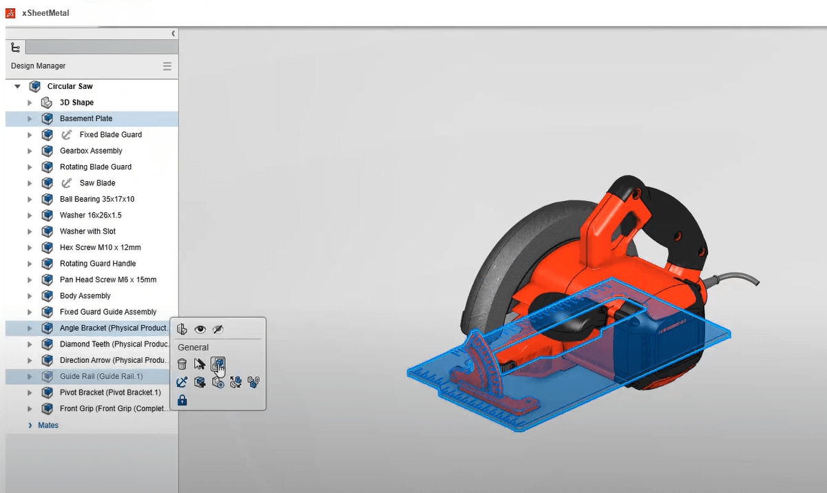
On the 3DEXPERIENCE® Works Platform, all applications are compatible with each other. With a seamless switch from xDesign to xSheetMetal, the toolbars in Don’s user interface update so he can stay focused on the task at hand. Don will start by isolating the components he plans to replace and creating the new replacement component. Copying the footprint from the original base will give Don a head start on the redesign. These holes are no longer necessary, so they can be removed. xSheetMetal includes advanced context recognition which means he’ll have quick access to the tools he wants, keeping his mouse cursor focused on the model.
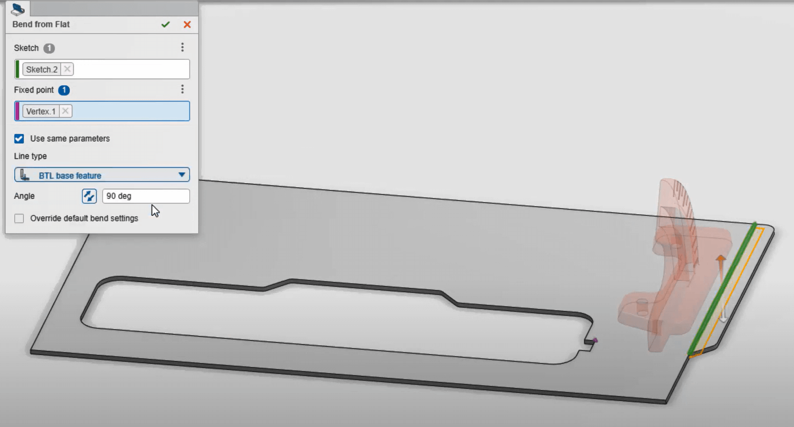
While getting started, he’s conveniently prompted to provide some overall sheet metal parameters to be used as default values, saving time on downstream features. Don hides the original base plate as he’s captured all he needs for this first feature. To enhance the design, he can bend this front edge upward so the base can smoothly glide over workpieces. The position of the bend is precisely defined by a sketched line and can be set to any angle.
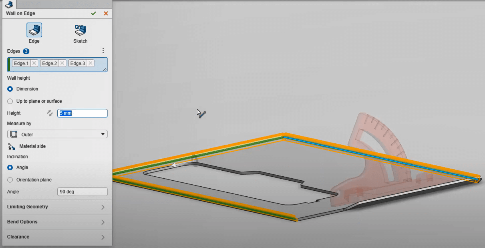
Not all sheet metal features require a sketch. In this case, Don selects the outer edges of the base to add some short walls. There are multiple alignment options to perfectly position the added material such as measurement criteria and material side. To confirm that the corners were trimmed per the default parameters, the current design can be flattened at any time.
The new cost-effective design requires a flange that mimics the angle bracket. Using the intelligent context-sensitive menu, Don creates a rough clearance cut for it. Once again, he converts the profile from the previous design and makes some small adjustments. To strengthen the connection to the base plate, he’ll remove these entities and close the gap by merging the endpoints. Even though this sketch was created out of the plane, it can still be used to create a ‘Wall on Edge’ feature.
The default tangent relief set earlier may not apply here, but Don can override it on-the-fly for this unique instance. Finally, he’ll want to adjust the material side to ensure the flange doesn’t interfere with other components. To account for manufacturability, Don can check for overlapping geometry in the flat pattern. With an overlap detected, he can measure the highlighted edges to assess how big of an adjustment needs to be made.
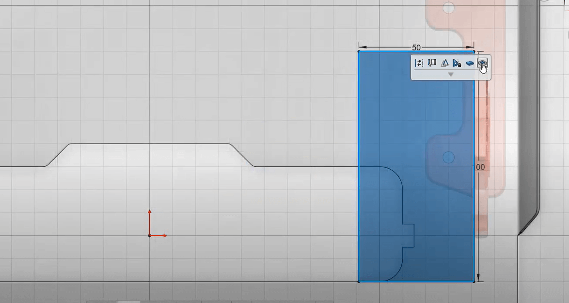
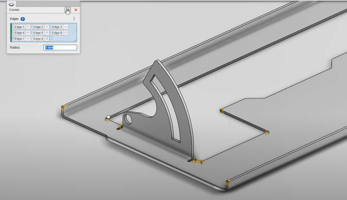
By subtracting the necessary clearance directly within the dimension field, xSheetMetal does the maths and reduces the risk of entering the wrong value. Sharp edges could be dangerous to the end-user and increase the difficulty to cut, so Don uses the ‘Corner’ tool to gather the edges and round them off. Another way Don can improve this design is by adding a guide rail. This will require a pair of clearance cuts through the side walls. Don starts with a rectangular sketch offset from the end face of the guide rail. By deselecting the ‘Link to Thickness’ option on the Cutout tool, the cut can extend through the entire model. Of course, all cut faces will be created normal to each surface to allow for a conventional laser, plasma, or waterjet cutting process.
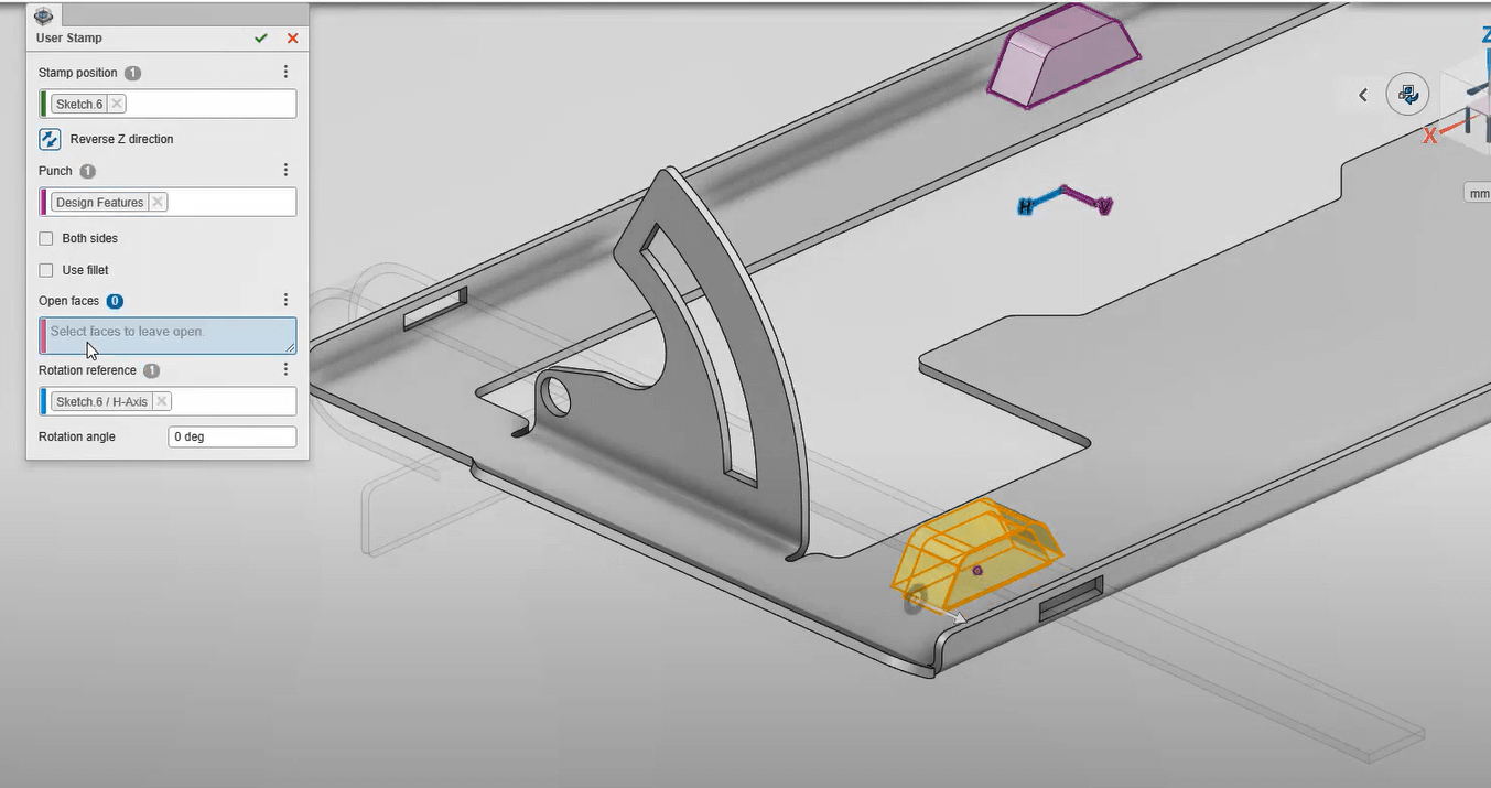
A slot needs to be created to hold the guide rail in place. In manufacturing, a feature like this would be stamped with a forming tool, and it can be modelled using the exact same technique. First, he’ll have to find the tool using the 3DEXPERIENCE® Works Platform’s powerful search capabilities. Then, he can define its location on the model with a sketch point. Finally, the ‘User Stamp’ feature allows him to specify the direction, fillet parameters, and which faces to remove from the resulting geometry.
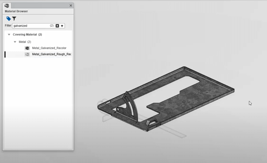
To give his new sheet metal component a realistic look, Don searches the extensive material database for a galvanised metal appearance and applies it to the part. These materials are perfect for making design reviews more engaging and also support downstream workflows such as product renderings.
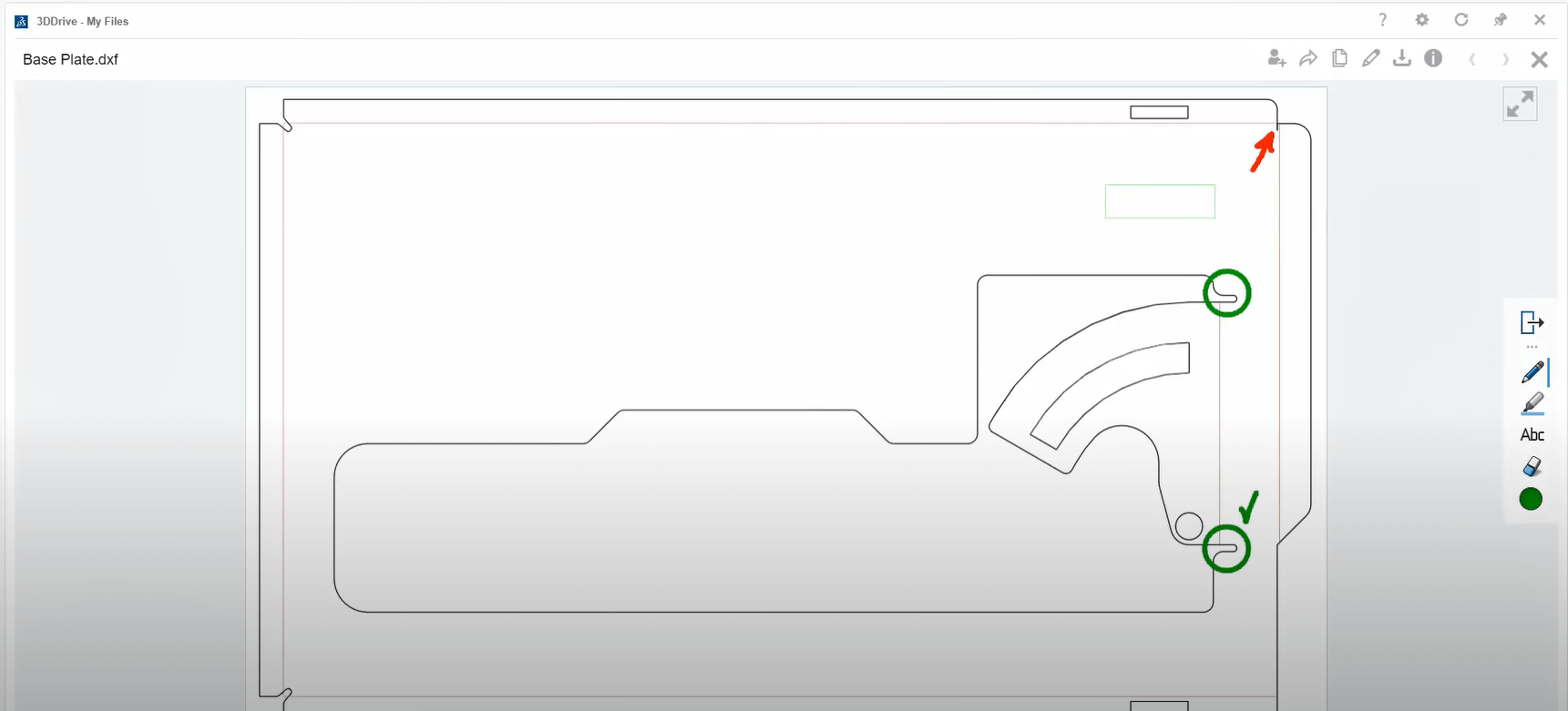
Don will supply his design to the cutting machine using the industry-standard DXF format. This will include the cutting profile, bend lines, and user stamps. Saving it to his 3DDrive allows him to share the file with anyone so they can view it and add markups using the 3DPlay app. Additionally, these markups can be shared with a community to notify key projects stakeholders and discuss further changes. Before closing his browser for the day, Don notices another component that will require a flat pattern before it can be manufactured. Unfortunately, this component was created using traditional modelling features like extrudes and cuts. Still, Don’s able to get the information he needs using the ‘Recognize’ tool to calculate an accurate flat pattern.
When you use the right tool, you can get your job done faster at a higher quality. The 3D SheetMetal Creator role on the 3DEXPERIENCE® Works Platform provides a purpose-built environment that’ll have your designs ready for manufacturing in no time.
3DEXPERIENCE® Works cloud-based design apps for Rendering
A team of design engineers have been busy evolving the aesthetics of a circular saw, along with finding ways to reduce manufacturing cost through creative sheet metal design. But before it can go to manufacturing, Material finish and colour selections have to be decided on. Let’s see how you can help accelerate the decision process and get this product to market with the powerful cloud rendering capabilities of the 3DEXPERIENCE® Works Platform.
Dan is working in the 3D RENDER role in order to kick off some product colour proposals. Creating a new rendering project, he has instant access to all of the current design data through the 3DEXPERIENCE® Works. Being new to this role, Dan immediately notices the lean user interface, which makes it easy to start creating some photorealistic renderings right away.
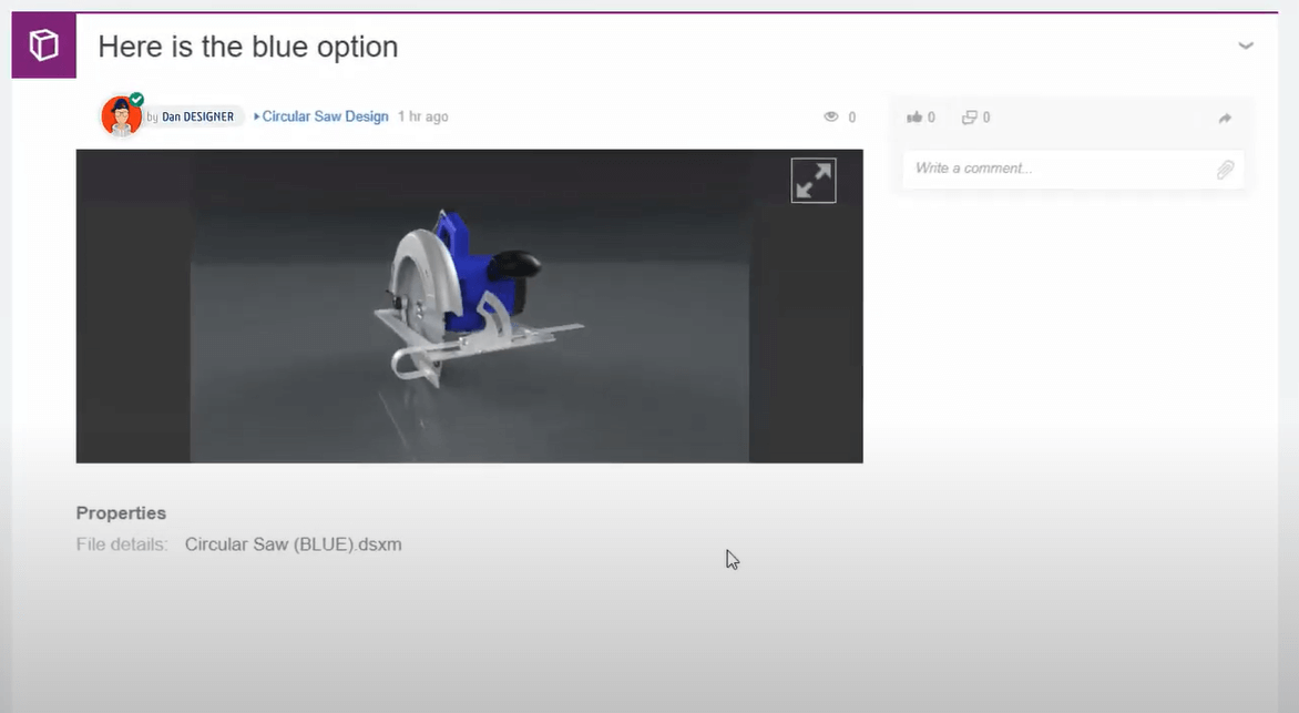
A handful of components in the circular saw already have appearances that were applied during the design phase since these are retained in the rendering project, so Dan can dive right into making a colour modification. Creating a new scene lets Dan modify the appearances while maintaining the original, changing red to blue for the housing, and a light grey on the blade guard.
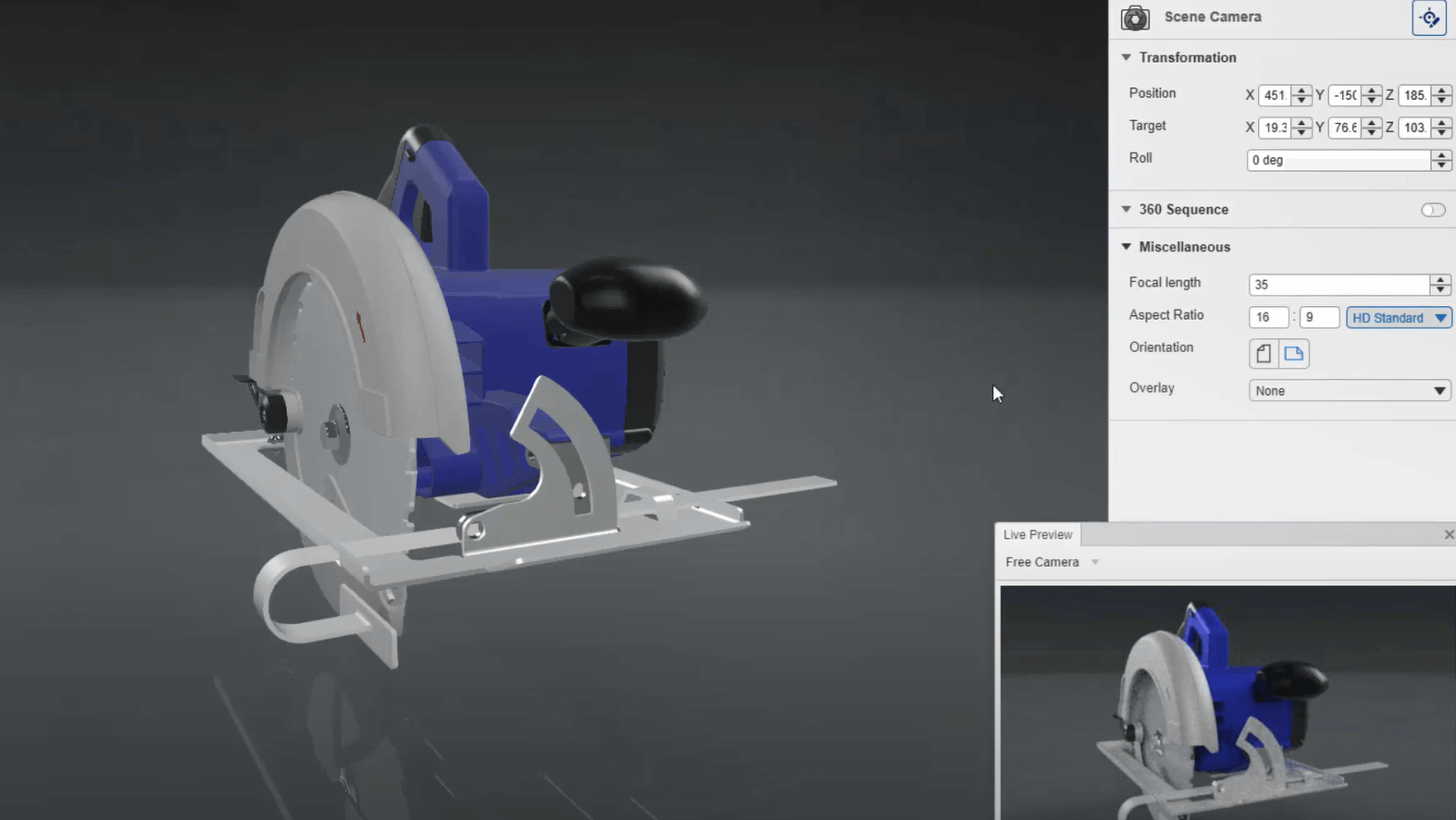
At any point, Dan can enable the rendering preview to check in on his progress. This is a perfect way to verify materials and colour selections are just right before moving to the final render. Simple camera settings can also be modified on-the-fly. Dan decides that a 35mm wide angle lens and modern 16:9 aspect ratio looks best.
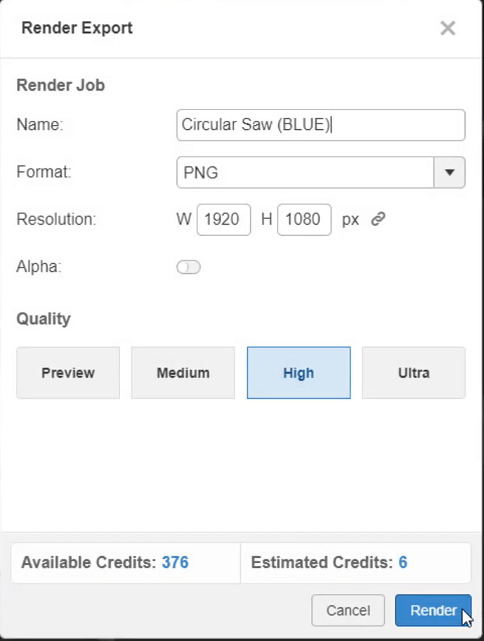
Now it’s time to render the project. Simple output options let Dan adjust his images to a standard HD resolution and high-quality setting. The necessary credits that will be consumed for this rendering job are calculated and displayed. These credits provide a scalable option that is calculated based on the project needs. With the click of the mouse, the 3DEXPERIENCE® Works takes over by rendering this image right on the cloud.
Returning back to the original variation, Dan will generate another rendering which can be done while the first image is being processed. This time, an interactive turntable will be used to extend a virtual walkaround to the rest of the team. The job is submitted and run side by side with his earlier request. 3D RENDER allows endless rendering processes to be done in parallel, never slowing Dan down from tackling his next task.
After only a few minutes, each rendering is complete and are ready to share. Dan has the option to download these locally, save to the 3DEXPERIENCE® Works Platform or directly post to the team’s collaborative SwYm Community, where everyone can view, comment and finalise their decision.
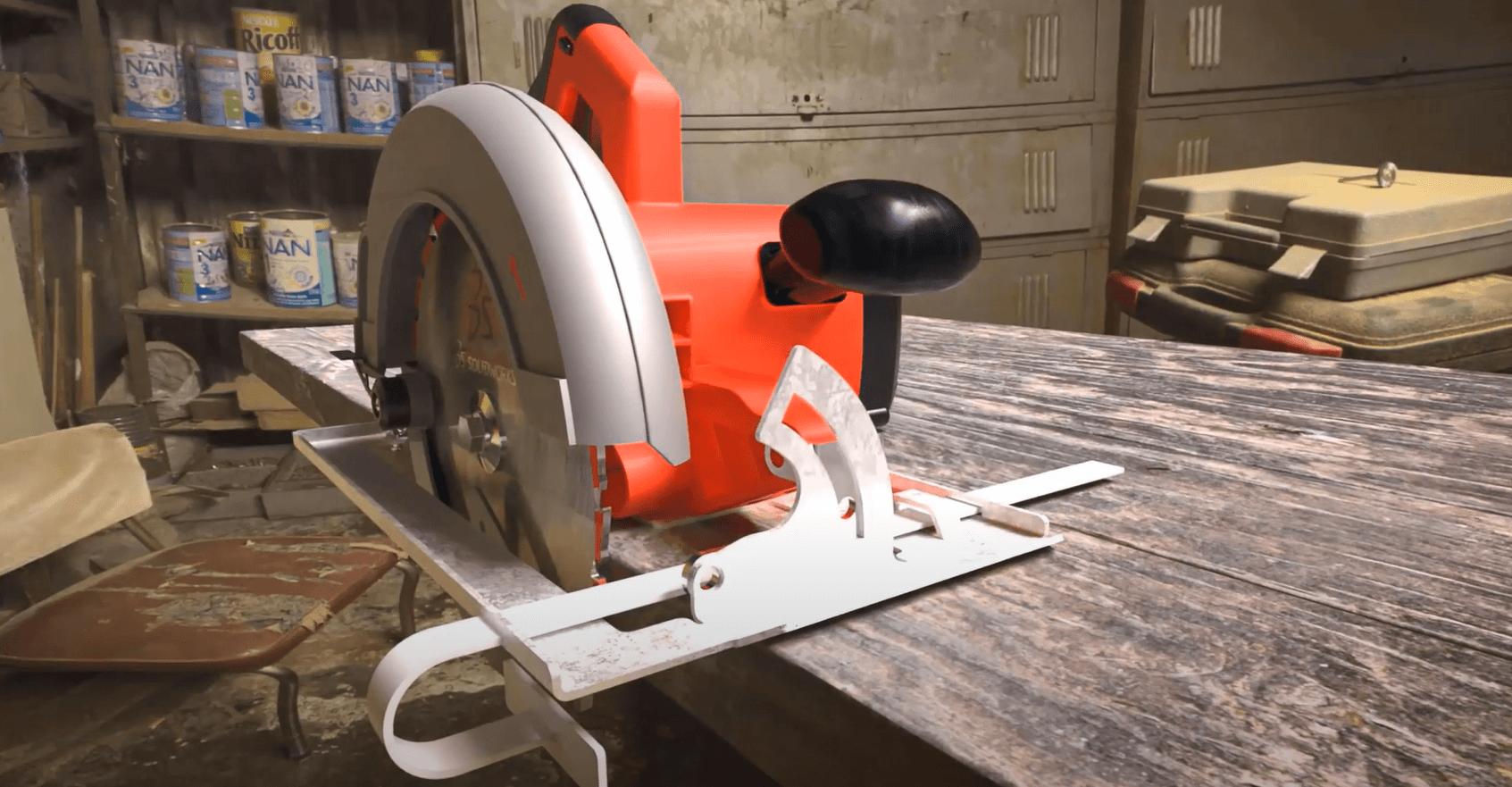
Now that the colour has been decided on, Dan’s next task is to generate some marketing assets. 3D RENDER supports complex materials as well and these physical-based representations of the saw blade will add the extra detail for the final outputs. A quick search, drag and drop and the custom material is applied. A glimpse of the preview window and Dan gets instant feedback of his material selection.
Other 3D design assets can be repurposed and added into a 3D RENDER project. Searching the team’s design library shows a woodworking table. Dan drags this in and positions both the table and the saw for the final output.
Applying an Ambience to the background adds a nice final touch. Just a few tweaks to the background-size, exposure and adjusting the camera perspective gives him the perfect shot. Dan is once again ready to send another project to the cloud. Using 4K resolution with the ultra high-quality rendering option, this image will be approved for publication in no time.
Whether you’re Creating quick renderings for internal design reviews, or generating professional-level marketing assets, 3D RENDER on the 3DEXPERIENCE® Works Platform provides an easy, affordable and scalable option for all users on any device.
About the author: Elite Applications Engineer, Lucy Davies, is one of our dedicated 3DEXPERIENCE® Works Platform technical engineers.


