
An introduction to how individual parameters in derived configurations are linked to changes made in the parent configs, except for specific items.
Configurations allow you to create multiple variations of a part/assembly model within a single file. They provide a convenient way to develop and manage families of models with different dimensions, components, or other parameters. Another underused area of configurations is derived configurations. The advantage of derived configurations is the bi-directional relationship they have with their parent configuration.
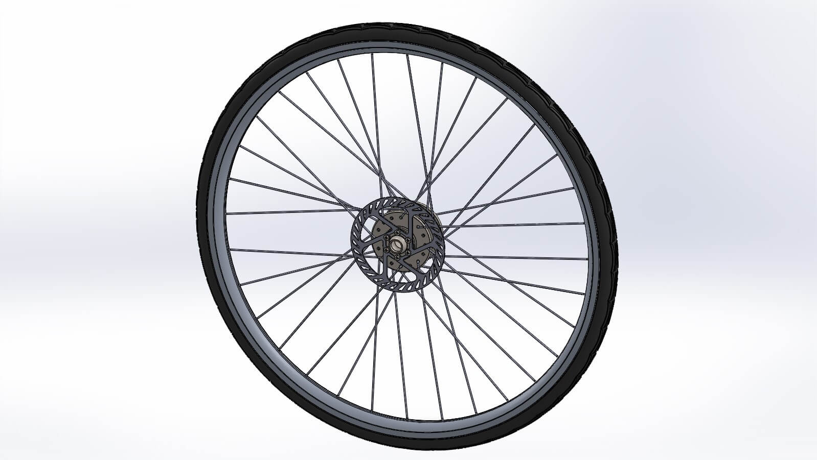
To highlight their use, let’s have a look at an example inspired by the Tour de France, held right here in Cambridge, of a bicycle wheel using derived configurations.
In this assembly example, some of the components are modelled using in-context relationships. This will help us show not only the suppression of certain components/features, but it will also enable the software to update the geometry to rebuild other components automatically. In the case of the bicycle wheel, the spokes and tyre are constructed with relationships to the spindle and rim. This means that the overall wheel diameter can be changed and they will update automatically.
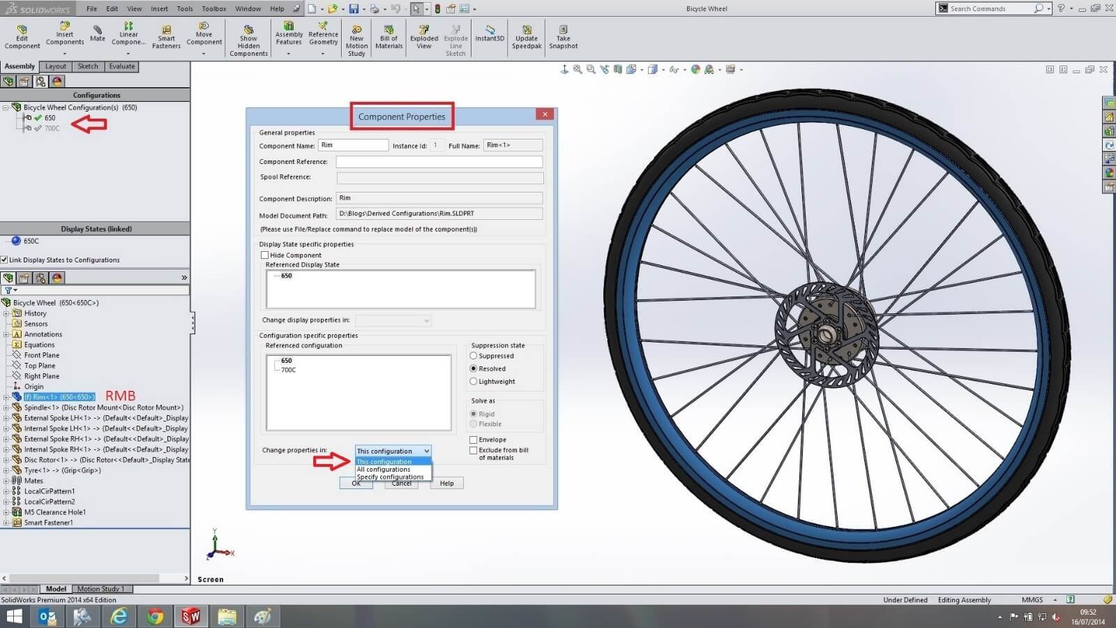
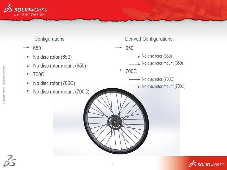
The first step to create our configurations and derived configurations is to think about how to display the variations that we want. The most common diameter bicycle wheel is a 700C, this will form the basis of our first configuration with a second at 650. At the ‘rims’ part level, the two sizes have also been created in their own configurations, this enables us to specify which part level configuration we can use in our assembly level configurations through the ‘rims’ component properties.
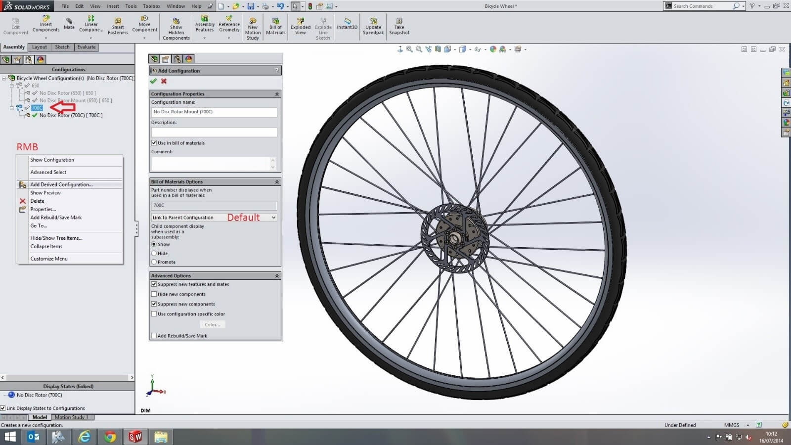
Now that we have our parent configurations, 750C and 650; we can proceed with adding derived (child) configurations for each. To add these, make sure the parent configuration is highlighted first; that way when you right mouse button click in the configuration manager and add, all the parameters in the derived configurations are linked by default to the highlighted parent configuration. This means if you change a parameter in the parent configuration, the change automatically propagates to the derived unless otherwise stated.
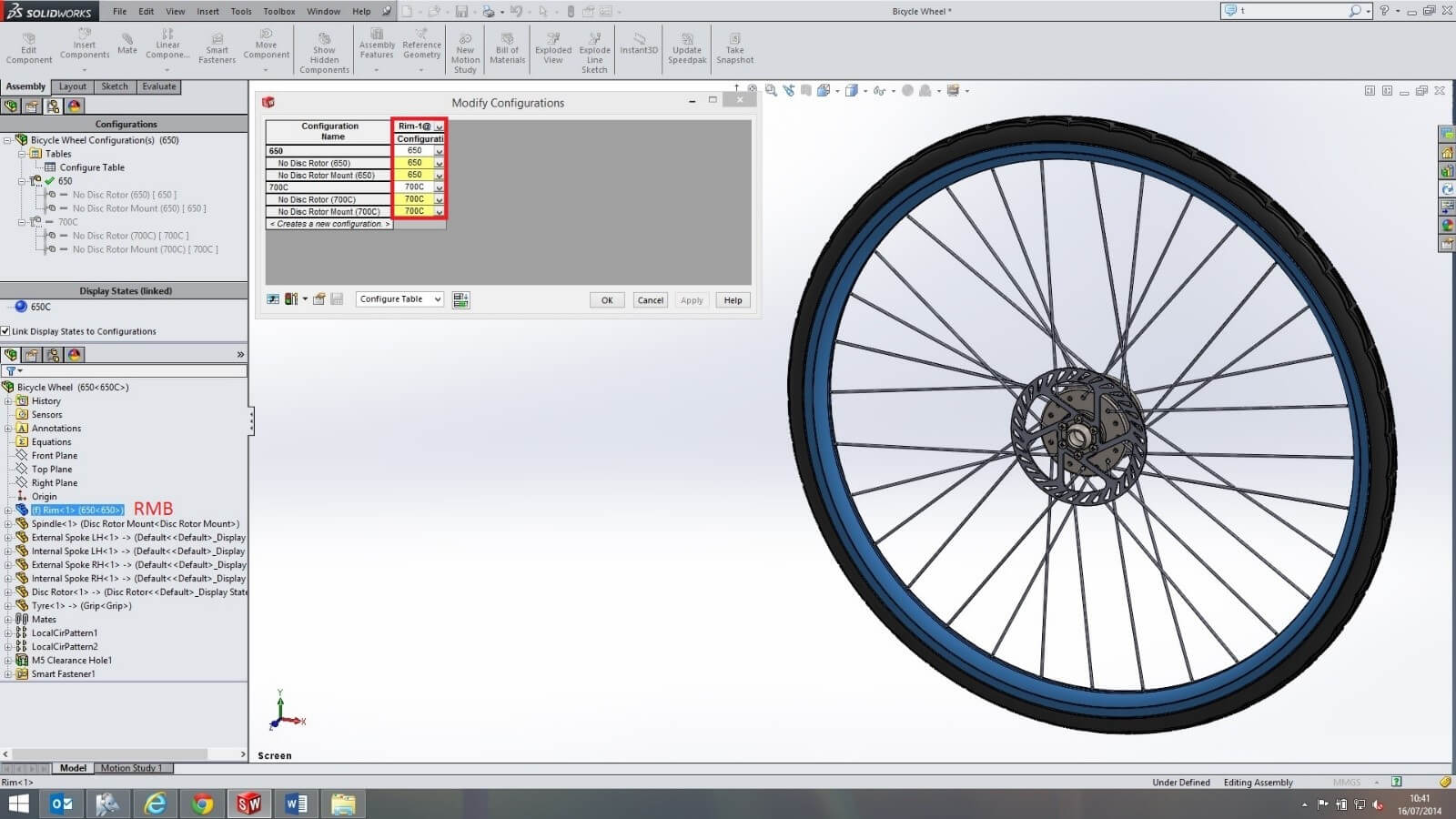
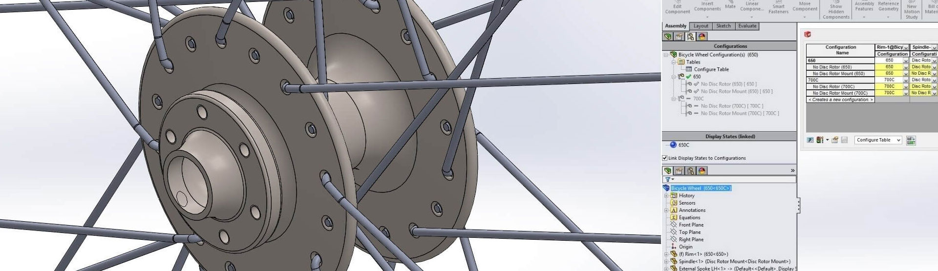
In all these derived configurations we want the size of the ‘rim’ to follow their parent. This has already been done for us when we created each derived configuration. If we right mouse button click on the ‘rim’ component and select ‘configure component’, we can see each derived configurationhas inherited their parents ‘rim’ configuration highlighted in YELLOW. In each of the derived configurations, the yellow colour represents that the ‘rim’ configuration is not specifically linked to its parent configuration which remains WHITE. We will adjust this for another component later in the blog.
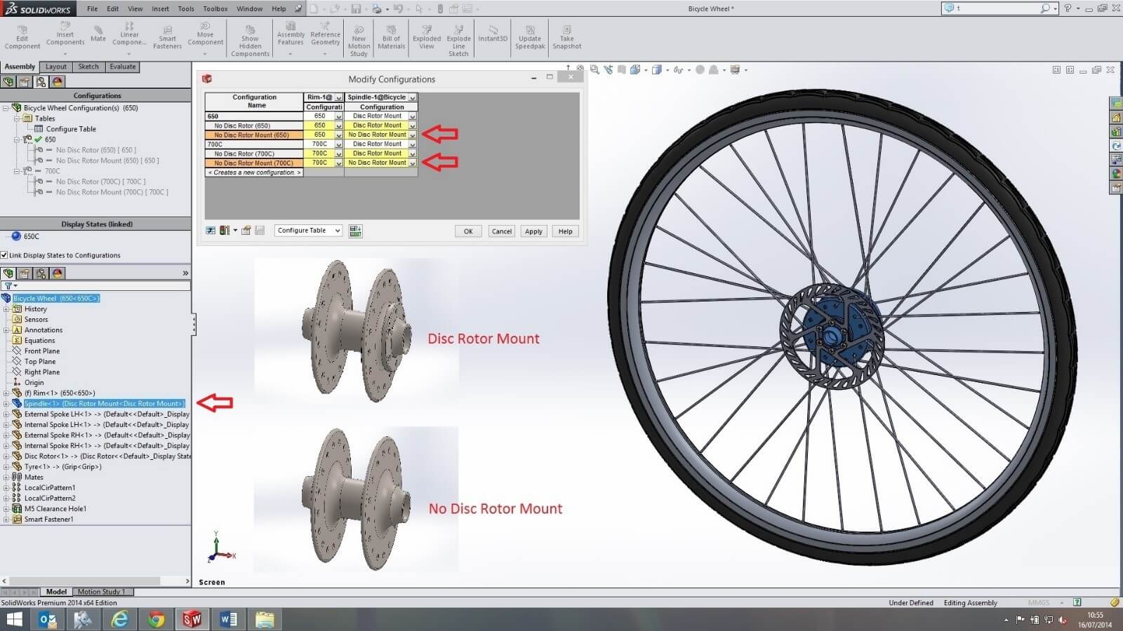
Adding another column for the ‘spindle’ by double clicking on the component from the feature tree, it is here we can choose which of the ‘spindle’ configurations to use for each of the derived configurations. Using the drop down arrow in the ‘no disc rotor mount’ configuration, the ‘no disc rotor mount’ configuration for the ‘spindle’ is selected which inherently keeps the cell colour yellow.
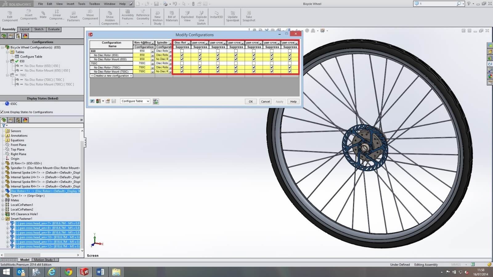
Now because the two top level parent configurations both have a ‘disc rotor’, we need to add that component and all the toolbox components to our ‘configure table’ for suppression in all the derived configurations. The derived configurations need not follow their parent which keeps their cell yellow when checked.
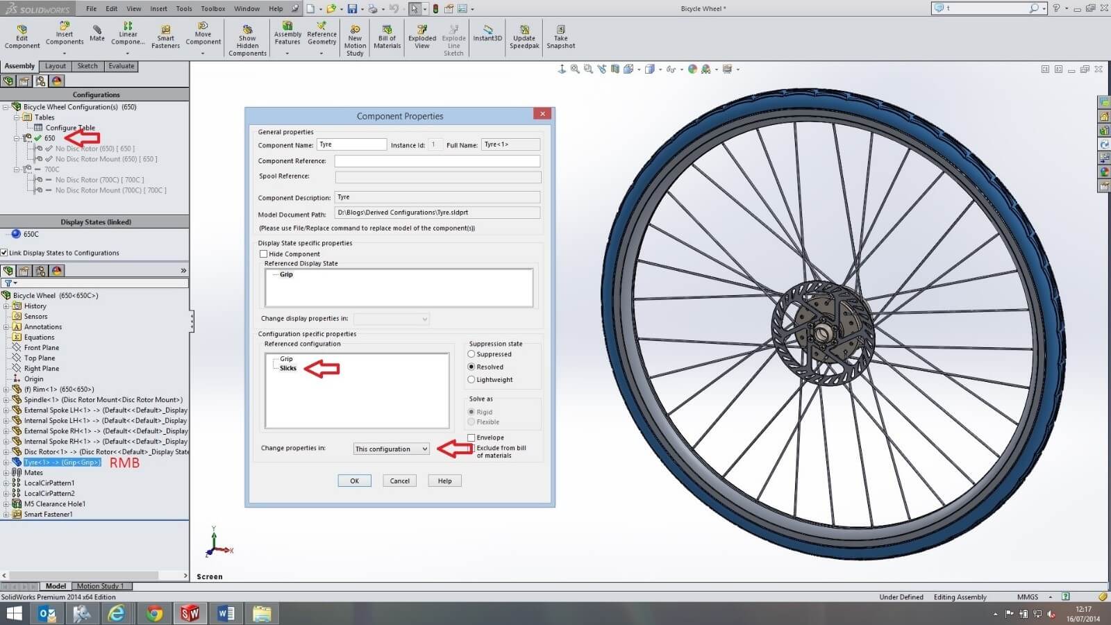
Now sometimes you may want components to be different between the top level parent configurations but to be the same for each derived configuration. We can achieve this by first activating the parent configuration ‘650’.In the feature tree,right mouse button clicking on the ‘tyre’ to open its component properties. We want the tyre to use the parts ‘slick’ configuration for this ‘650’ parent configuration.
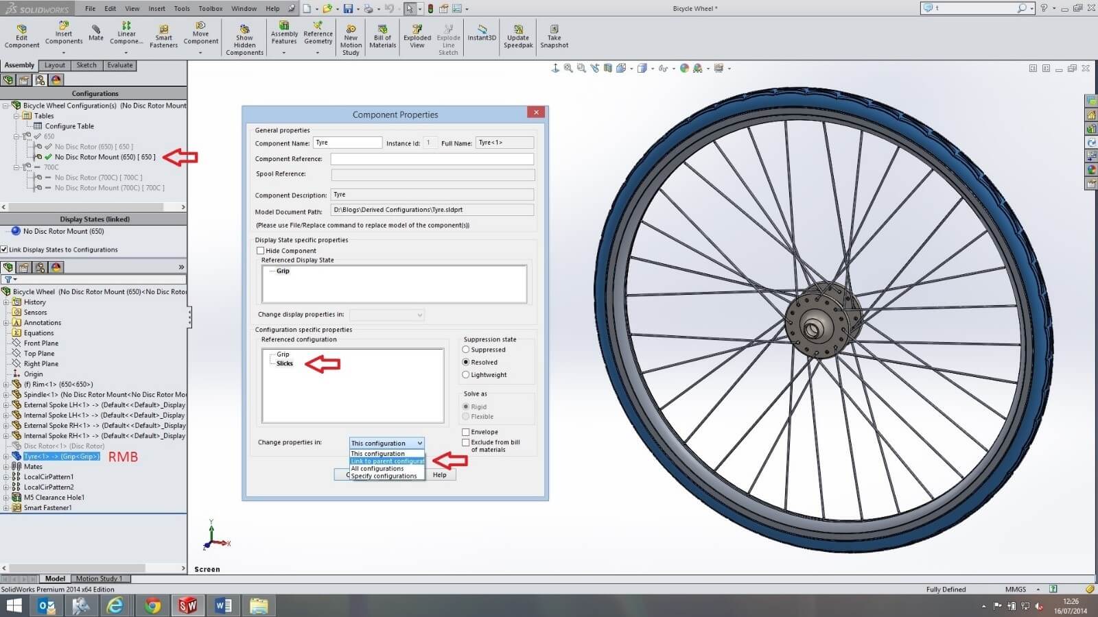
To have the same ‘slick’ configuration in each of the derived configurations like that of their parent ‘650’, we need to complete the same process for all the derived configurations, but use the ‘link to parent configuration’ option.
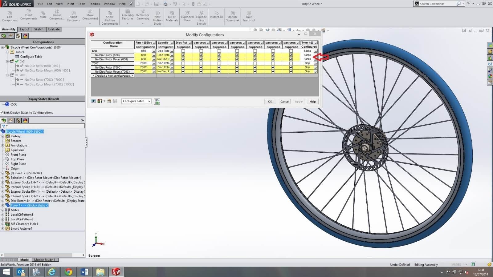
When opening the ‘configure table’ and adding the ‘tyre’ component, it can be seen that each of the derived configurations under the parent ‘650’ are white, this indicates that they are now following their parent configuration. Having saved the ‘configure table’, we can now easily change all the ‘650’ derived configurations from using either the ‘slick’ or ‘grip’ configuration by the drop down arrow in the parent configuration cell.
In the configurations example above, if we wanted to make a change to specific configurations, we would have to change each configuration. So, for an example, if we need to change a dimension within any configuration starting with ‘650’; we would have to alter three configurations, or use the ‘specify configuration’ option.In the derived configurations example above, a change to the top level ‘650’ configuration would automatically populate downwards to the tabulated configurations unless otherwise stated.
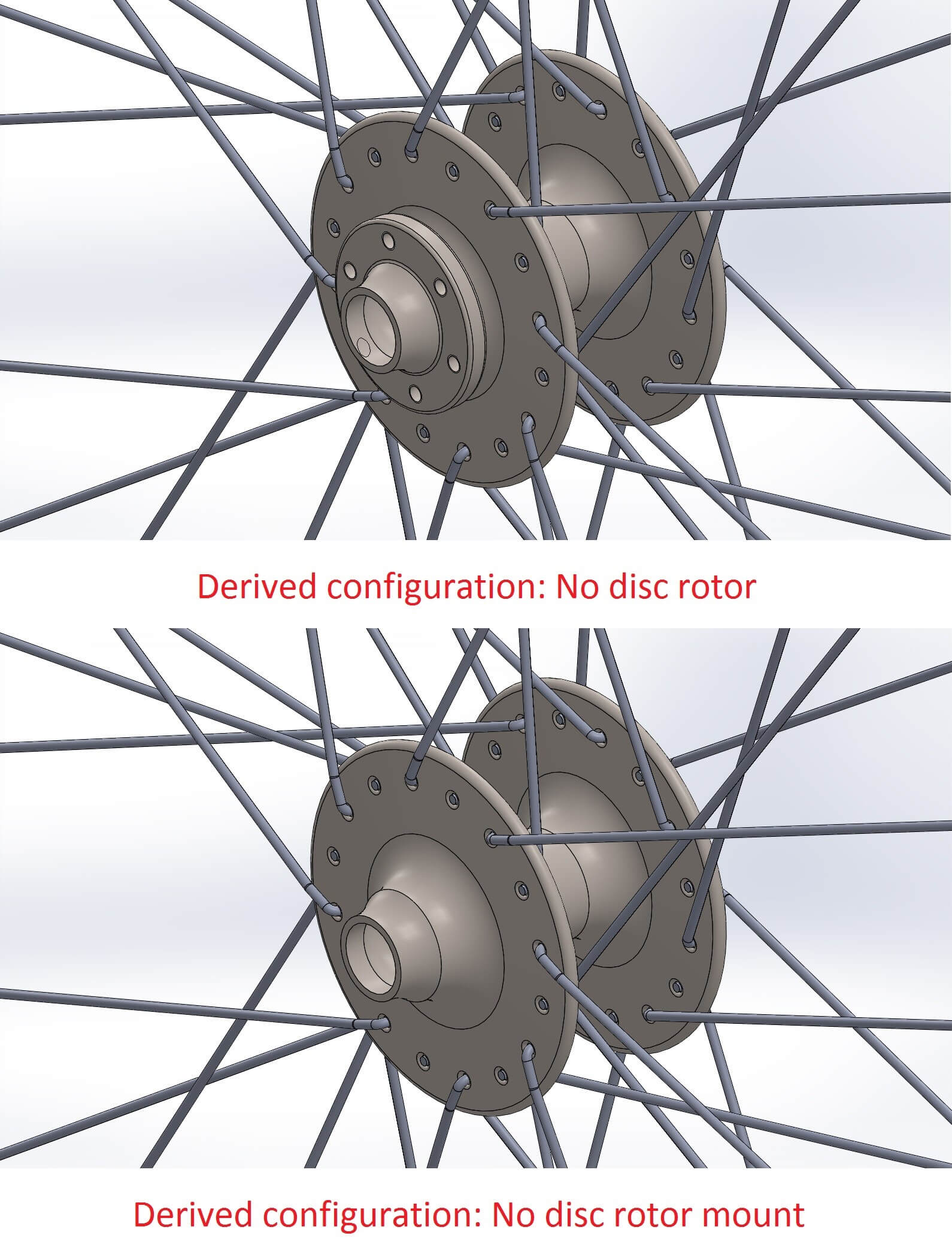
The process of creating derived configurations can take some thought and be lengthy, however in our example, it shows how derived configurations can be an advantage to us. Derived configurations have allowed us to create parent-child relationships within the individual ‘650’ or ‘700C’ configurations. This enabled the ‘rim’ configurations ‘650’ or ‘700C’ to flow from the parent configuration to its derived configurations. Yes this could have been achieved by creating multiple configurations for each variation like above, but derived configurations allow us to control the ‘tyres’ configurations for each ‘650’ or ‘700C’ parent. The ‘tyre’ component in the derived configurations could then be linked to their parent. If we had created configurations for each, we would’ve had to change the ‘tyre’ in each configuration manually resulting in timely design changes. The control over our derived configurations has further additional benefits because of the override of any configurable parameter so that it is no longer linked to its parent configuration. The ability to change a dimension, configuration or suppress a component like the ‘disc rotor’ in each of the derived configurations enabled us to create the different variations for each of the main ‘650’ or ‘750C’ wheel diameters.
We hope you found that useful!
Have you seen our blog archive where we have posted plenty of helpful articles? We also have a fantastic video library filled with easy-to-follow videos on a number of topics inspired by other SOLIDWORKS users – take a look.
Also, don’t forget to follow us on twitter for daily bite size SOLIDWORKS tips, tricks and videos.


