
There are a set of Forming Tools for punching Sheet Metal models Inside the Design Library in SOLIDWORKS. You can find these items in the Forming Tools folder. There are a number of useful tools here; ribs, lances, Louvres and extruded flanges, to name some of the categories.
It is quite easy to open the models found in these folders and to change their sizes. However, If you are looking to create a custom shaped forming tool, there is a process you can follow to achieve the desired result.
Here’s how to do it:
The first step is to create the desired geometry that you would like to punch into your model. Initially this can just be a very basic sketch and extrude drawn out on a flat plate. Fillets can be added to the inside corner, to give a radius to the sheet metal model.
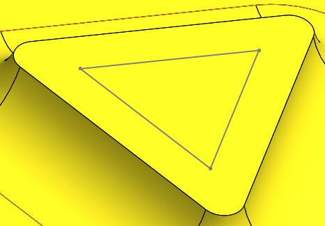
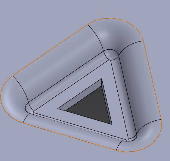
In the example below, the middle of the top face will remove a triangle on the sheet metal model, to allow this to work, a sketch has been drawn to represent the area to be deleted. This sketch needs to be projected onto the model, the split command needs to be used to make two faces on the top (as there is currently only one). The Split Line command can be found under – Insert > Curves > Split Line.
One thing to note when creating the geometry for a forming tool is that the internal radius on the inside corner will limit what thickness of sheet the forming tool can be applied to, a 4mm radius can only be used on a maximum 4mm sheet. Any thicker and the sheet metal model will intersect.
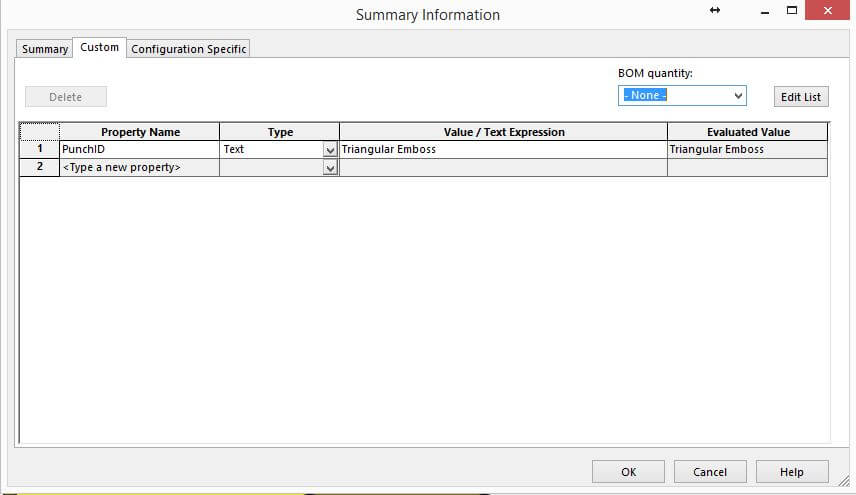
Once the forming tool shape is complete it is advisable to add a Punch ID in the custom properties menu (File>Properties). By adding this information, any Punch tables that are created from resulting sheet metal models will read through some relevant information from the custom forming tool.
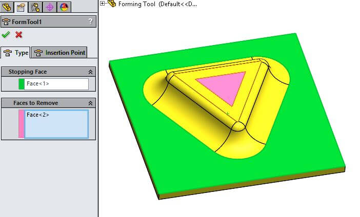
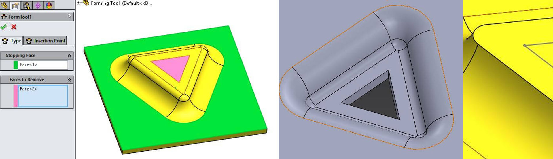
The forming tool command can now be used to setup the model. This can be launched from the sheet metal toolbar. Two property boxes are contained within this command, one for a stopping face in green, and one for faces to be removed in red/pink.
The file is now complete, when saving the file there are two options;
- Saving the files in the Design Library\Forming Tools\ as any SOLDIWORKS part (.sldprt/.sldlfp/.sldftp)
- Saving the files in any folder on your machine, but saving it as a SOLIDWORKS forming tool part (.sldftp)
All of the file types needed can be found on the File>Save As menu. Drop down the “save as type” to find the various options.
We hope you found that useful!
Have you seen our blog archive where we have posted plenty of helpful articles? We also have a fantastic video library filled with easy-to-follow videos on a number of topics inspired by other SOLIDWORKS users – take a look.
Also, don’t forget to follow us on twitter for daily bite size SOLIDWORKS tips, tricks and videos.


