
With the upcoming prospect of SOLDWORKS 2016 Beta (end of June) we thought it would be a good time to go back over a few favourite updates from the 2015 release.
One of these we really like was Drawing Zone Lines.
Most drawing borders we have seen include a grid style referencing on them – so around the border would be number and letters creating a grid. It would be good drawing practice to include the grid reference in any revisions you made, or for locating detail or section views. Prior to the 2015 release, this grid location would need to be added manually.
Typical Example:
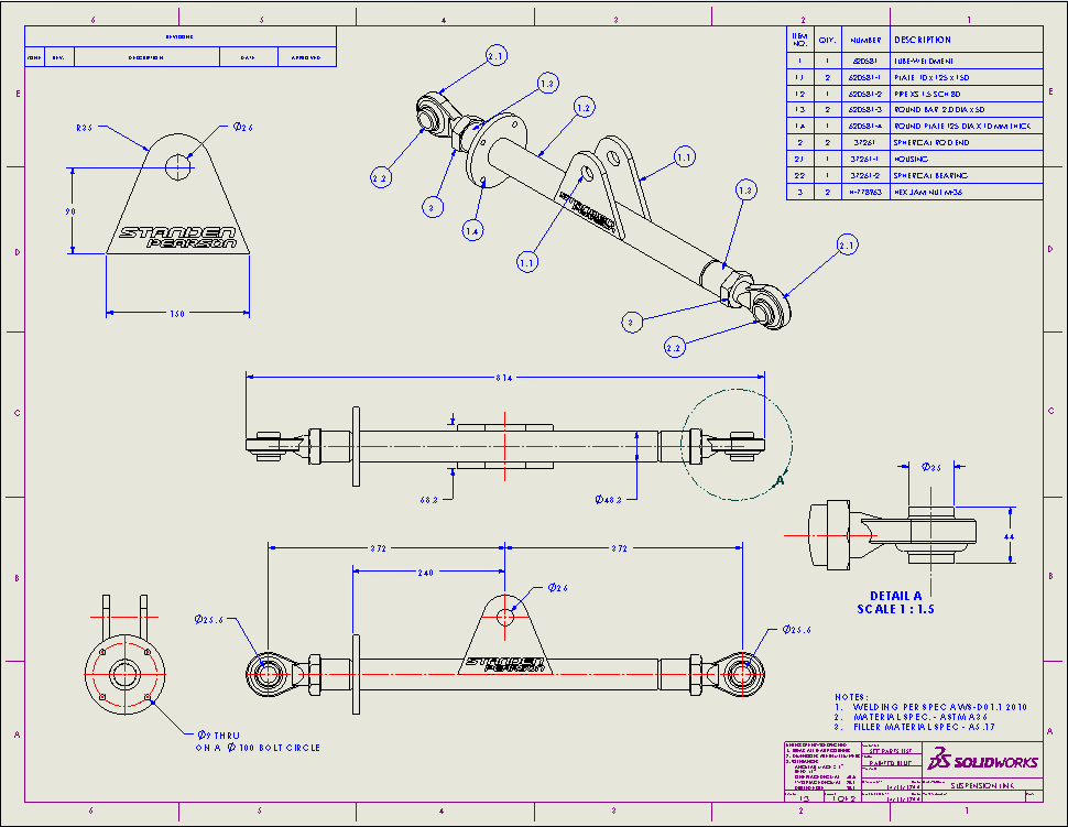
The same drawing (and drawing border) in 2015 can have Drawing Zone Lines added. It’s a pretty simple process to set up too.
Firstly, you will need to ensure your border carries the vertical and horizontal splits and characters as shown in the above example (You can have more or less if you want to).
If you then go to the View menu, you can turn on the Zone Lines. This will show up with the default number of zones lines. You will need to modify these to suit your border. The changes are performed in the Sheet Format, so you will need to right click on the sheet and select “Edit Sheet Format”
Once you are at Sheet Format level, you need to right click again and select “Zone Tag Editor”
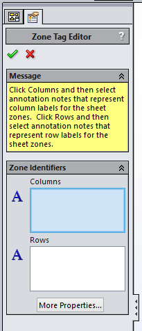
This tag editor allows us to associate the text around the border with the defined columns specified – ensuring that if you use the zone line functionality (in a revision table or view label) that they give the correct reference.
If you need to increase or decrease the number of zone lines, select “More properties” first, and you can change the quantities.
Here you can specify the margins to use and whether or not you’re equally spacing the lines or offsetting from the centre.
You can then add the column labels into the column section, and the row labels into the row section.
We can exit the sheet format now.
If you have a revision table on your drawings, we can add an extra column to it – by inserting a column in the normal way. But you will see there is a new category called “Zone” if we include this, and re-save our revision table template, it will automatically populate with the zone where the revision is made.
Once configured correctly, we can re-save the sheet format (File – Save Sheet Format, .slddrt) and the associated drawing template file (File –Sava as, set dropdown to “Drawing Templates” .drwdot).
Now that’s setup, we can have a look at what it does!
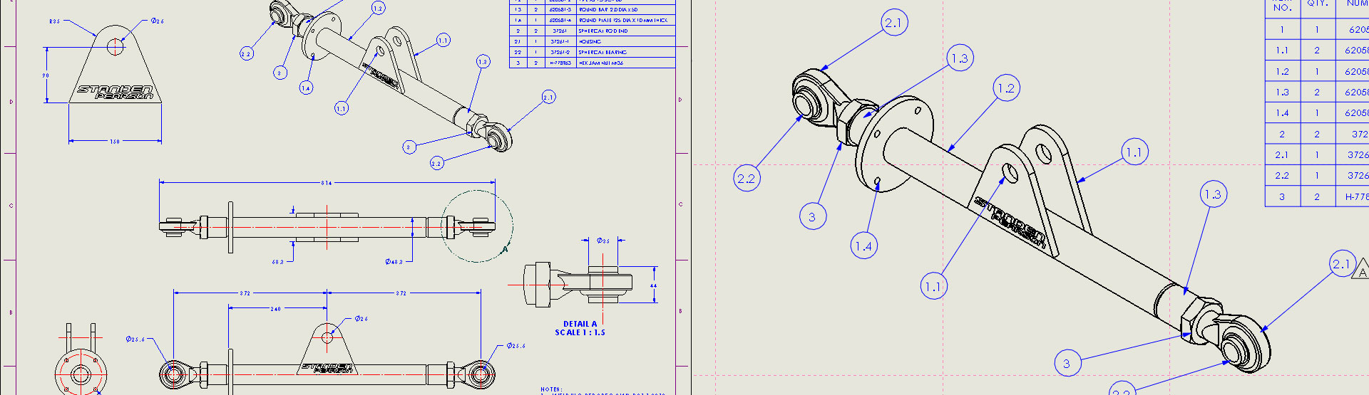
If we add a revision to out revision table in the top left of our drawing, and place the revision triangle next to the balloon 2.1, you will see that the Zone column automatically populates with “D2”, as the triangle has been place in Column 2, Row D.
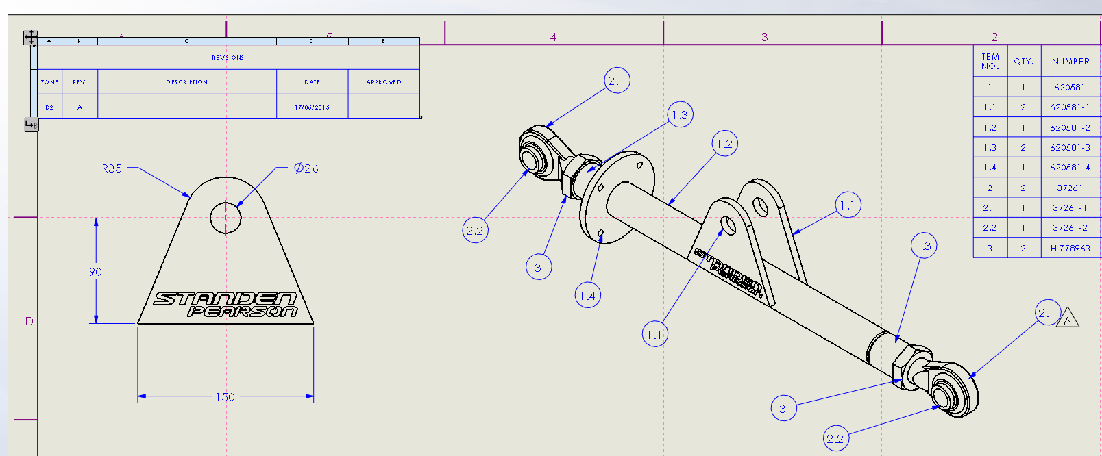
That’s the first benefit to using Zone Lines.
It can also be helpful for view locations as well – especially if you are creating multi-sheet drawings.
A new tool was added to the annotation toolbar called “Location Label”.

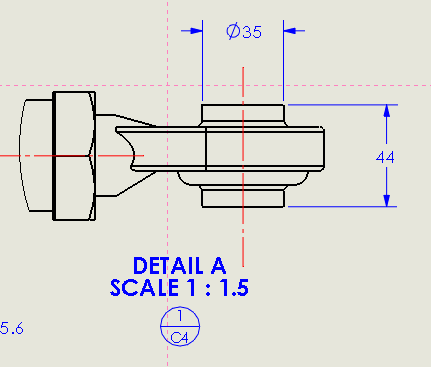
If you don’t have in on your toolbar by default, right click on the command manager and select “Customise”, tab “Commands. Click on the “annotations” heading and then drag the location lable tool onto your toolbar.If we then select the tool, and click on “Detail A” it places the location label underneath the detail view and automatically fills in the sheet number and Zone reference into a split balloon.
The balloon style is fully customisable along with the text that goes into that balloon, so you can configure them to your company standard.
Because, by default, the location label includes the sheet number, if we move the detail view onto a different sheet, it retains the sheet number where the parent view is – so in our example the balloon stays exactly the same.
If we place a location label on the detail view circle though, and then move the detail view to a second sheet – the location label updates to suit.
A nice addition to the 2015 release and one that we feel was overlooked.
We hope you found that useful!
Have you seen our blog archive where we have posted plenty of helpful articles? We also have a fantastic video library filled with easy-to-follow videos on a number of topics inspired by other SOLIDWORKS users – take a look.
Also, don’t forget to follow us on twitter for daily bite size SOLIDWORKS tips, tricks and videos.


