
In this video we’ll look at typical example of
creating and documenting a machined part using SOLIDWORKS.
[Video transcript]
Sketching a profile
We begin by sketching a profile for the base of our machined part. Familiar sketching tools are available to us, such as lines, arcs, rectangles, splines, and many more. Sketch patterning tools are also available such as mirror. We don’t have to worry about the size of the profile as we sketch it, as it will resize itself correctly when we add constraints such as dimensions. We can then extrude it to the correct depth.
Adding some holes
Next we add some fixing holes, as you can see we have a large library of holes to select from including counterbores, countersinks, tapped holes, clearance holes more. We simply choose the hole type we want position them where we want them. We add another rectangular extrude, before sketching this profile on its side face. Notice the width of this profile is defined by the rectangular extrude. I’ll sketch a circle concentric with the radius above it. Again we’ll extrude it to the required depth.
Next up we’ll add an M8 tapped holes around the bore on a PCD on 105mm. We have a large variety of patterning tools available, here I use circular pattern to define how many instances of the hole very quickly. I’ll go with 4. I now need to add a recess to the bore.
Use the library
Rather than sketching out every feature required, its possible to build a library of commonly used features that crop up between multiple designs. Here I have a recess with port library feature saved. I simply drag it on to my part, key in a few dimensions and that’s my recess complete. Another patterning tool available is mirror, I can choose to mirror all the features that make up the triangular boss.
We continue to build the model using similar tools before, and finish the model with a number of fillets – That’s our model almost complete!
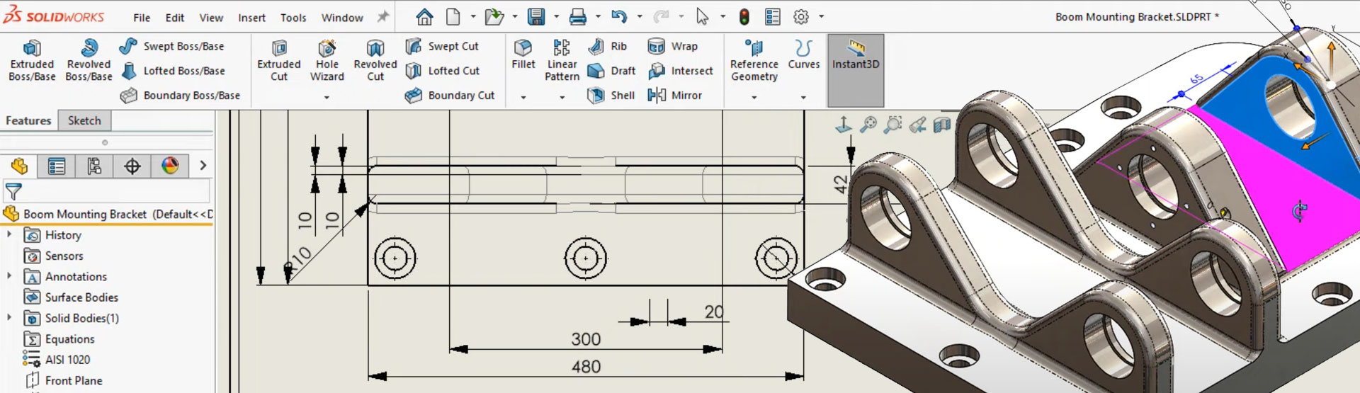
Applying materials
We now need to apply a material. We have large library of materials that we can select from. I’ll choose AISI 1020. The material properties applied will allow me to calculate an accurate weight. I can even run a simulation on the part to see how it would react to a force or pressure.
Creating the technical drawing
We now move on to creating the technical drawing. As you can see the orthographic views are created automatically for me, I just need to place them in my drawing sheet. I can add hole callouts and it will present the information clearly. I can also add dimensions these are correct as per the model and not effected by the scale of the sheet. It’s also possible for us to bring through the dimensions we used to construct the model. SOLIDWORKS does a great job of laying them on the views with minimal amount of tidy up required. I can create section views and detail views in just a few clicks. I’ll just add a few dimensions here.
Making changes is easy
Inevitably designs change, Here’s where SOLIDWORKS really comes into its own.
In this case, we need to increase the thickness of the triangular boss. We can just select the dimension controlling the thickness and drag it. As you can see the model updates live on the screen. We’ll also increase the tapped hole count around the bore from 4 to 6 and that’s our changes complete.
The great thing with SOLIDWORKS is its associative, so any changes you make to a part will automatically propagate to wherever its used. Whether it be a drawing or an assembly. If we switch back to the drawing you can see all the drawings views have automatically updated with the changes you have made as have the dimensions and the callouts. This means your drawings are always going to be accurate and it will help to eliminate errors that are often incurred during change procedures.
So, to summarise:
- We can create models quickly using intuitive sketching tools and features
- We can save commonly used features as library features for reuse
- We can easily modify our design by typing or dragging dimensions
- Orthographic drawing views are created automatically and dimensions & callouts can be imported
- Section views & detail views can be created in a few clicks
- SOLIDWORKS drawings are associative – If the model changes the drawing views automatically update
- Drawing views are less prone to error


