
When you are designing components that need to fit together, it is sometimes difficult to understand what shape they need to be. The standard approach is adding the components into an assembly and then measuring one against another to understand if what you have produced will fit together. This can be a time consuming process and involves a number of attempts editing the parts to get it spot on. It can also leave your design open the error, if the design changes and you forget to update all the models for instance.
A different approach is to add one or more components into an assembly which could be considered the master or driving components. Once these have been placed in the correct location, further components which could be considered as slave or driven can be added into their correct position in the assembly in a state which is not quite complete. We will then use reference geometry from the master or driving components by editing the part in-context, this will allow us to finish the design on these slave or driven components. This approach allows us to quickly make changes to the driving components and have peace of mind that all the remaining components will still fit.
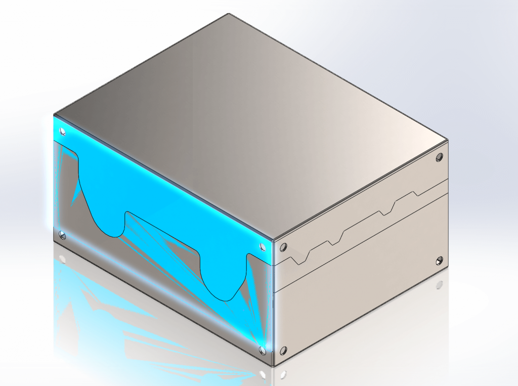
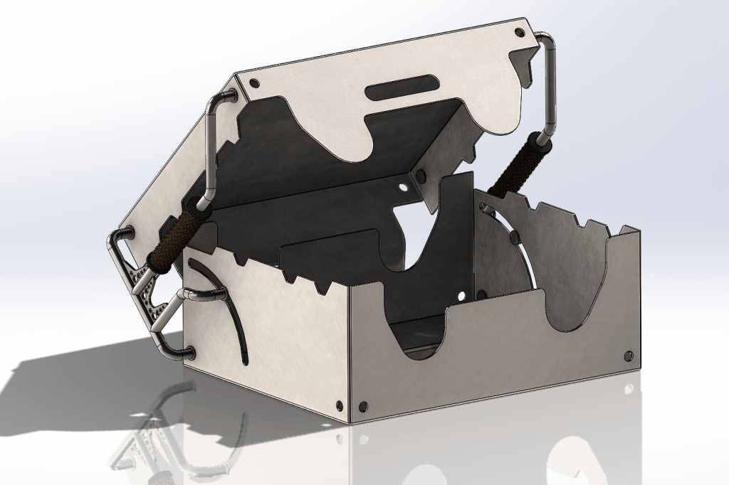
Here is a metal box that has some examples of how the in-context approach can work.
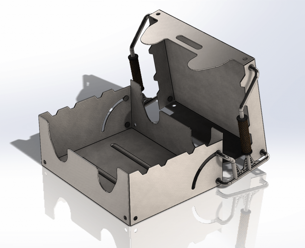
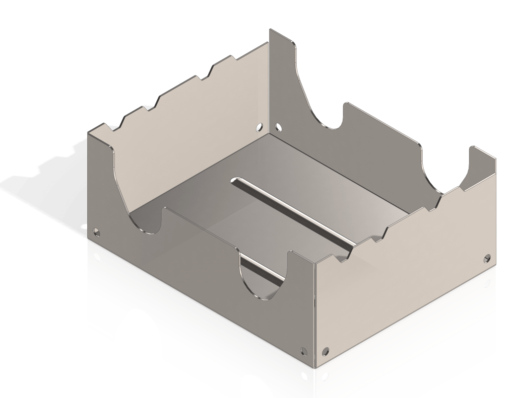
The first step is to put the driving component into an assembly. In this case it is the lower half of the metal box, this half has a complex upper edge which we want to offset and transfer to the top half of the box.
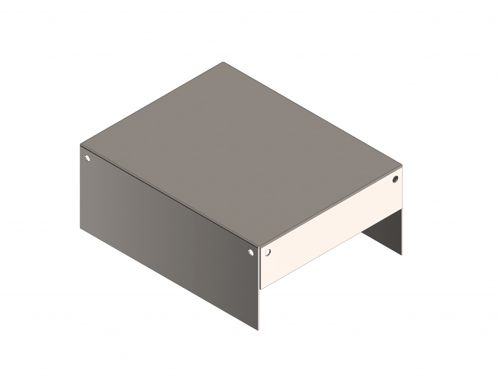
Now that the lower half of the box is in place we will insert the top half of the box into the assembly and position it correctly. Note that there are now interferences between the two components.
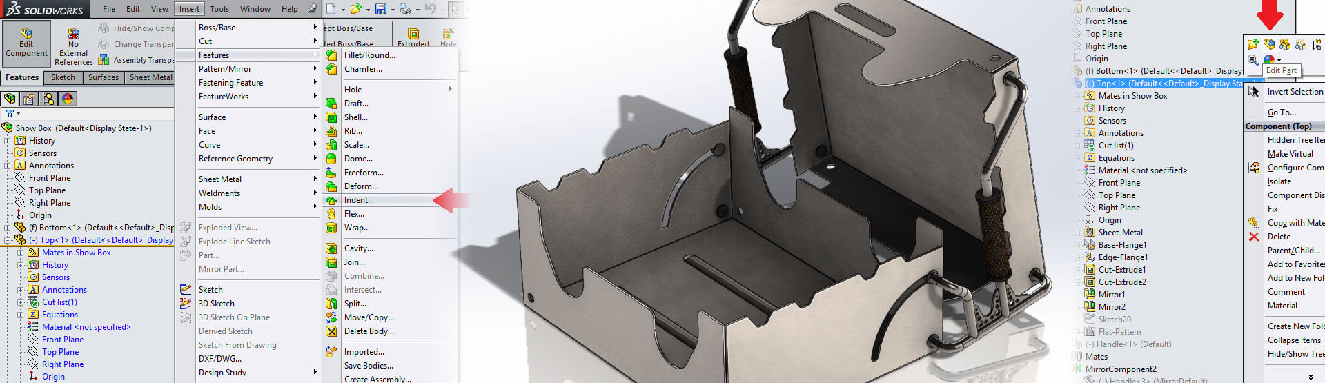
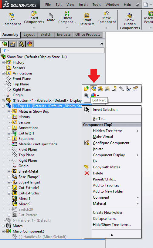
We will now edit the component in-context to produce the necessary cut to remove the interference. To do this right click on the component either in the tree or in the view port, then select “edit part” from the menu.
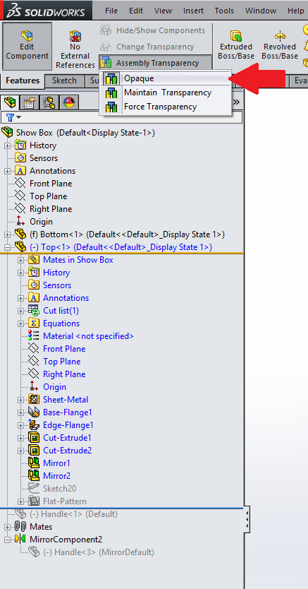
It is important that the assembly transparency is set to opaque, this will allow us to select other component geometry within the assembly as a reference.
When we are in edit mode, we can use all the functionality that we would have at part level and a large proportion of commands can be used in-context. You can tell if you have entered “edit part” mode by looking at the tree and seeing if the item you are editing is in blue. In this example we will use the indent command (located under insert>features menu) to cut the top half of the case back using the lower half as a reference.
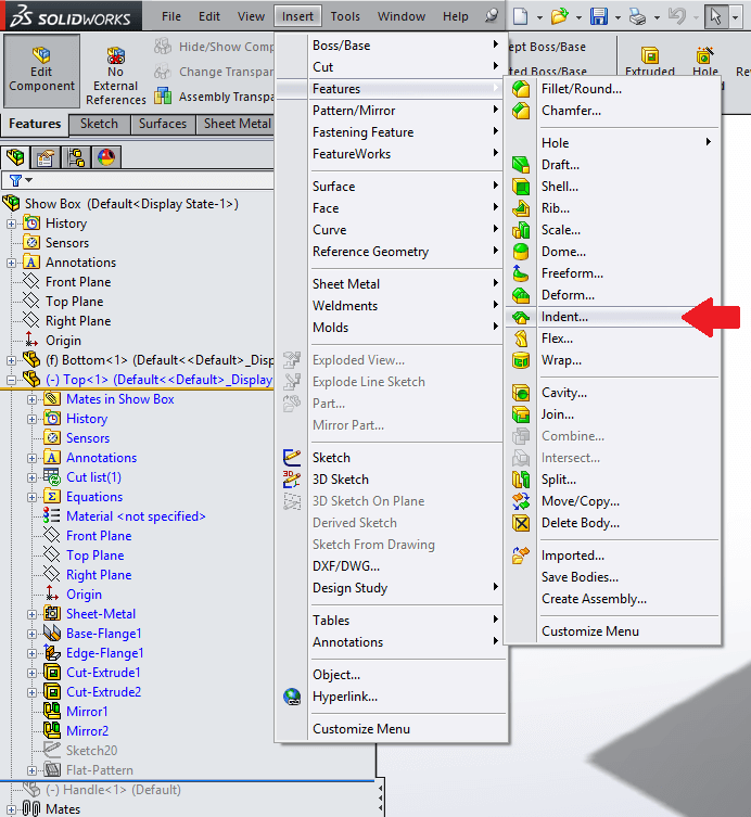
The indent tool is normally used when you wish to form geometry around another body. It does have another function which is similar to the subtract option located within the combine feature, this allows us to cut one body away from another. In the command you can select “cut”. This will allow us the cut a reference body (lower half of the box) away from the target body (top half of the box). This command also allows us to include an offset around the referenced body.
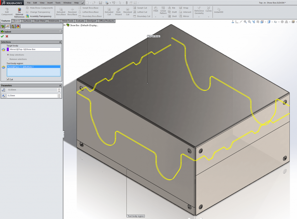
Now that the indent feature has been added, you can see in the tree that “indent 1” has the symbol -> after its name. This tells us that the feature or the sketch it uses has been created in-context.

We will now add a handle into the assembly and mate it in place. Note that the handle has one interference on the lower arm, the lower half of the box will need an arc slot cut added to it. This will allow the handle to rotate backwards allowing the box to open.
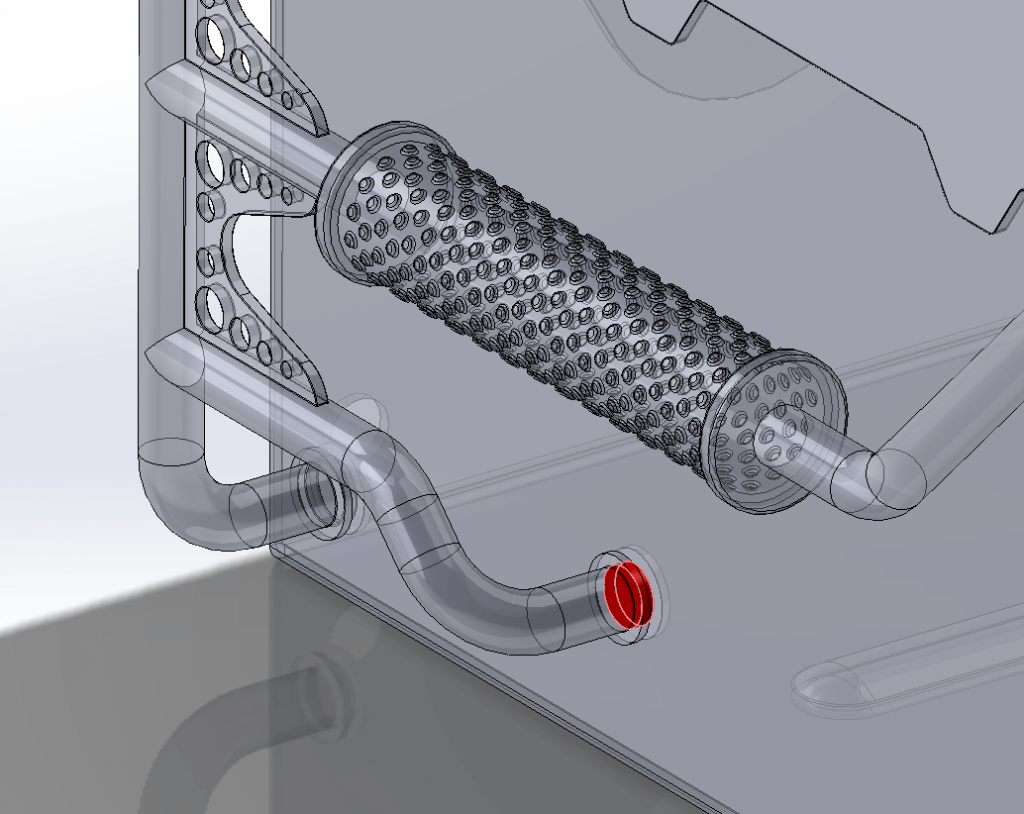
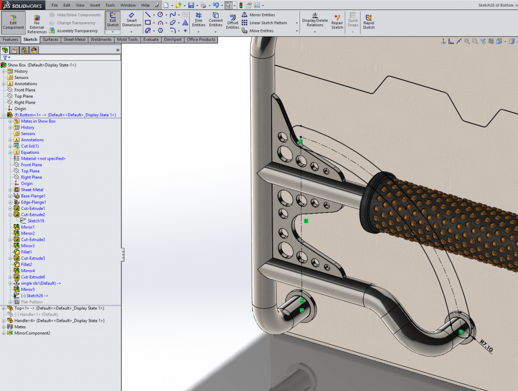
We will do this by editing the lower half of the box in the assembly and creating a sketch which will reference the position and size of lower arm on the handle. This will mean that if the lower handle arm length is changed, the slot cut will adjust position maintaining the correct shape.
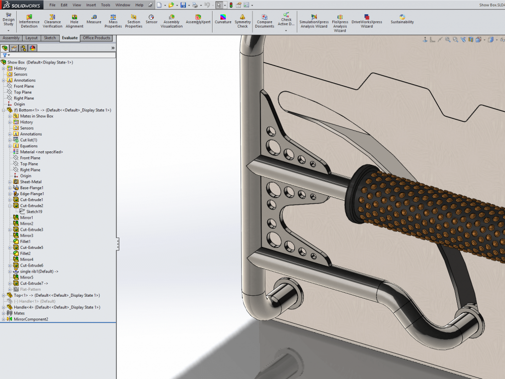
Once the sketch is created, we can continue to create the slot cut feature using “edit part” mode or switch to the part file and finish the cut there. Remember to exit “edit part” mode in the top right corner when finished.
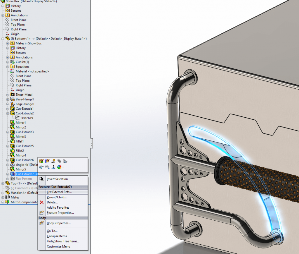
It is important to understand that this creates a dynamic link, so if the components move the indent and the cut will update to reflect the change. Therefore if your assembly has movement, it is important to lock the references on in-context features before you move the components. To do this, right click on the in-context feature you wish to lock the references of, then click on “list External Refs”.
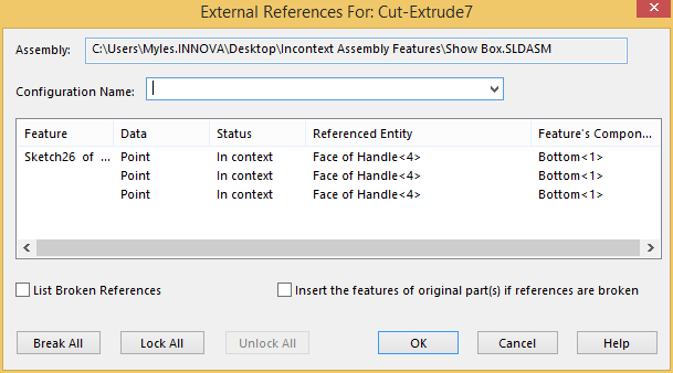
This window will allow you to lock the external references for that component. Once the lock button is pressed the feature or sketch that was based on the external reference will not update to the new location of the referenced entity. When you lock a feature or sketch the -> will change to ->*, this shows that the references have been locked.
If a change is needed at a later date, you can simply go back and unlock the features in the same way. Just remember to move the components back into the original position before unlocking the references.
Another option is to break references, this is permanent and can’t be undone. Therefore unless you are certain that you will never need to update the component, lock references is normally the better option. When you break references the symbol on the end of the name will change to ->X
Now the references are locked we can go ahead and open the box.
We hope you found that useful!
Have you seen our blog archive where we have posted plenty of helpful articles? We also have a fantastic video library filled with easy-to-follow videos on a number of topics inspired by other SOLIDWORKS users – take a look.
Also, don’t forget to follow us on twitter for daily bite size SOLIDWORKS tips, tricks and videos.


