
In this video we’ll take a look at creating a structure in SOLIDWORKS Weldments.
[Video transcript]
In this video we will be running through the creation of a weldment structure, specifically, this pallet dispenser.
Every weldment starts with a sketch, and with more complex structures such as this 3D Sketches make weldment creation simple.
This structure will be built up from multiple sketches: The base conveyor, the upright cage and the feet.
Standard weldment profiles can be downloaded from the SOLIDWORKS Content section in the design library. You can also create your own custom profiles, but in this video we will be using the ISO standard.
To start, I will select structural member and create the legs of the structure, we can either select parallel sketch lines, or continuous sketch lines to build structural member groups.
Once selection is complete, I can click new group. This allows me to build up another group which may not be parallel or continue on from the initial selections, in this case the cross supports.
As I make these selections SOLIDWORKS will automatically trim each corner and joint. This can be seen at the purple dots.
Click the green tick to create the structural members.
Next, I want to create the larger, rectangular beams. This must be done in a new structural member command as I am going to use a different profile, in this case. A 80 by 40 rectangle.
I can now repeat the process for this.
You’ll notice that these members do not automatically trim against the legs. This is because they are part of a different command. I will clean these up later on. For now, I will adjust the location of the member using locate profile, We use point selection to make the change , allowing the member to sit ontop of the legs.
If you spot a mistake, modifying weldments is straight forward. In this instance, I have missed a leg. Simply edit the feature, select the group and add the line. New members will automatically be trimmed against.
I will now finish off the base, locating the profiles to make sure everything aligns. Again, we can see the angled members are trimming to the horizontal beams with no user input required.
Onto the final weldment structure. I will now select the parallel uprights, these can be put in to 3 groups. I want to make sure the horizontal beams are perpendicular to these. To do this, I can use the alignment tool. This is especially useful when working with non square designs. I could not achieve this individual alignment if I selected all the horizontal beams as a single group, so separation is required.
As I mentioned before, joints are automatically cut at each purple dot. You can manually alter these by selecting the dot and altering the trim order. Here, I want a mitre.
The structure has now been created, but there is some final modifications and checks to be done. We can use the trim & extend tool for the cleanup operation. I will show you 3 examples:
- Extending our 80 x 40 profile to line up correctly
- Trimming our uprights to stop when they reach the base
- And finally, converting this corner into a mitre.
I will repeat this process to the rest of the model…This took me a minute or so.
Next, I am going to add the feet using a standard boss extrude. I can then pattern this across to all legs using a sketch driven pattern. I need to make sure that I pattern the body, not the feature otherwise the information will not feed into the cut list correctly.
I will now add a colour and upright panels.
You will notice that I have 3 cut list folders. These are none weldment bodies. We can create a bounding box for each to automatically allocate a description which details the size of panel required to produce the part.
next, some gussets and weld beads.
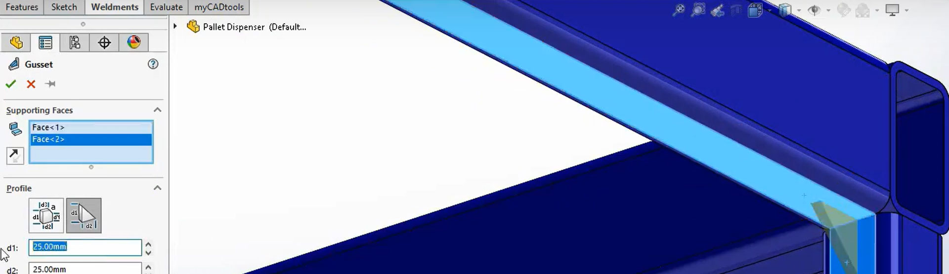
Starting with the gussets, select 2 adjoining faces and it will automatically create a preview. Alter the settings to suit. I will repeat for each leg. Again, notice the cut list folder, we can create a bounding box and even modify the name if necessary.
Next, a weld beam, this works using the same principle, select two adjoining faces and the weld preview will be created, change the settings to suit.
The part is complete, we now need to produce a drawing.
Drag in a view and then add a weldment cut list, finishing with some balloons. For the cut list you can also add angle cut details if required, as this information is captured as you model.
Modifications are easy, changing a dimension will propagate to all features and related documents. Lets finish with one final change. altering weldment profile and adding in some end caps. Again, all modifications will propagating to all features, cut lists and referenced documents.
Thank you for watching!


