
When working with imported models in SOLIDWORKS one of the main disadvantages comes in the fact that there is no design tree, a “Dumb Solid” is all you normally get. Models contain no parametric intelligence and can often be very difficult to edit the shape of. Let’s take a look at some of the tools that can be used to change the shape of these designs, allowing a user to adjust a model in several ways.
Delete Face
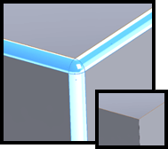
The Delete Face command (Insert>Delete Face) is very useful for deleting and sometimes patching or filling in areas of a model. Selecting delete and patch in the delete face tool can be used to remove areas of a model you don’t want.
For example, it can be used to delete a fillet from the corner of a model. Additionally, it can also be used to remove holes, or cuts and boss geometry extruding from a face.
The delete and fill option within the command can be used to smooth out multiple small faces from an imported design.
Move Face
The Move Face command (Insert>Move Face) can be used to modify the shape of existing geometry in an imported design. There are three options; offset, translate and rotate.
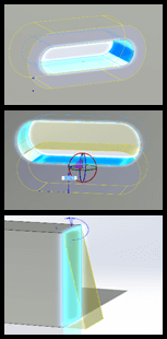
The offset option provides a simple and effective way to make existing geometry larger or smaller (for example, increasing the size of a hole) this can be done using a blind dimensional value from the selected face or relative to other geometry. Translate will allow any geometry to be moved within the bounds the face it sits on. Rotate allows a face or group of faces to be rotated to a new position.
In a situation where there is no design tree the move face tool allows for simple changes on existing geometry.
Replace Face
The Replace Face tool (Insert>Replace Face) can be used in order to replace faces from your part model with newly created surfaces. It will adjust any adjoining faces in order to match the new face. This allows certain faces to be replaced, without editing the existing design geometry.
Featureworks
FeatureWorks is one of the options which can pop up when you first load an imported model. The intention with this command is to give the user the ability to interpret the models geometry and create a design tree. This command works best in those situations where the user can see which commands have been used, and easily read the geometry as a set of features. So no good for complex surface geometry unfortunately.
FeatureWorks comes with the Professional and Premium packages. When turned on in the Add-ins menu, it will ask the user if they’d like to recognise features (upon opening an imported model). The options for this command can be accessed from Insert>FeatureWorks, from this menu the functionality of this command can be expanded to create sketches and auto insert Relations/dimensions – Taking this step makes the design easier to edit.
The functionality of this command is more extensive than the others. If you are interested in knowing more, take a look at this video:
Deform
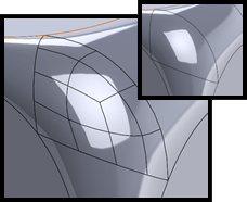
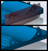
The Deform tool (Insert>Features) is a very powerful tool in the software, allowing the user to deform in three main ways; matching a model edge to a curve, deforming the faces of a design with a sketch point, or using another Solid in the model to deform a body.
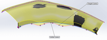
In the example above, a model edge has been moved by defining another curve to match the shape to (Curve to Curve in the Deform tool). The advantage of this technique is that the sketch/curve that’s created can be an accurate representation of the desired geometry, without having to know the existing imported shape. There are options to define certain faces/edges as fixed geometry, as shown by the purple edge. Options can also be set which allow the user to adjust the level of geometric accuracy too.
The Deform tool is best used in those scenarios where complex changes need to take place on a model to form an organic shape. For simpler examples it would be easier to use the “face commands”.
The tools described here show that when working with imported models there are a range of tools which can be used to modify the geometry of your design, even if you have no design tree. It certainly shouldn’t be thought of as a dead end for your design process. Have a go with these commands and see how you get on!
We hope you found that useful!
Have you seen our blog archive where we have posted plenty of helpful articles? We also have a fantastic video library filled with easy-to-follow videos on a number of topics inspired by other SOLIDWORKS users – take a look.
Also, don’t forget to follow us on twitter for daily bite size SOLIDWORKS tips, tricks and videos.


