
In this tutorial we’ll be looking at every facet of the Automatic Border tool, but before we get started, let’s take a look at the following SOLIDWORKS drawings terminology:
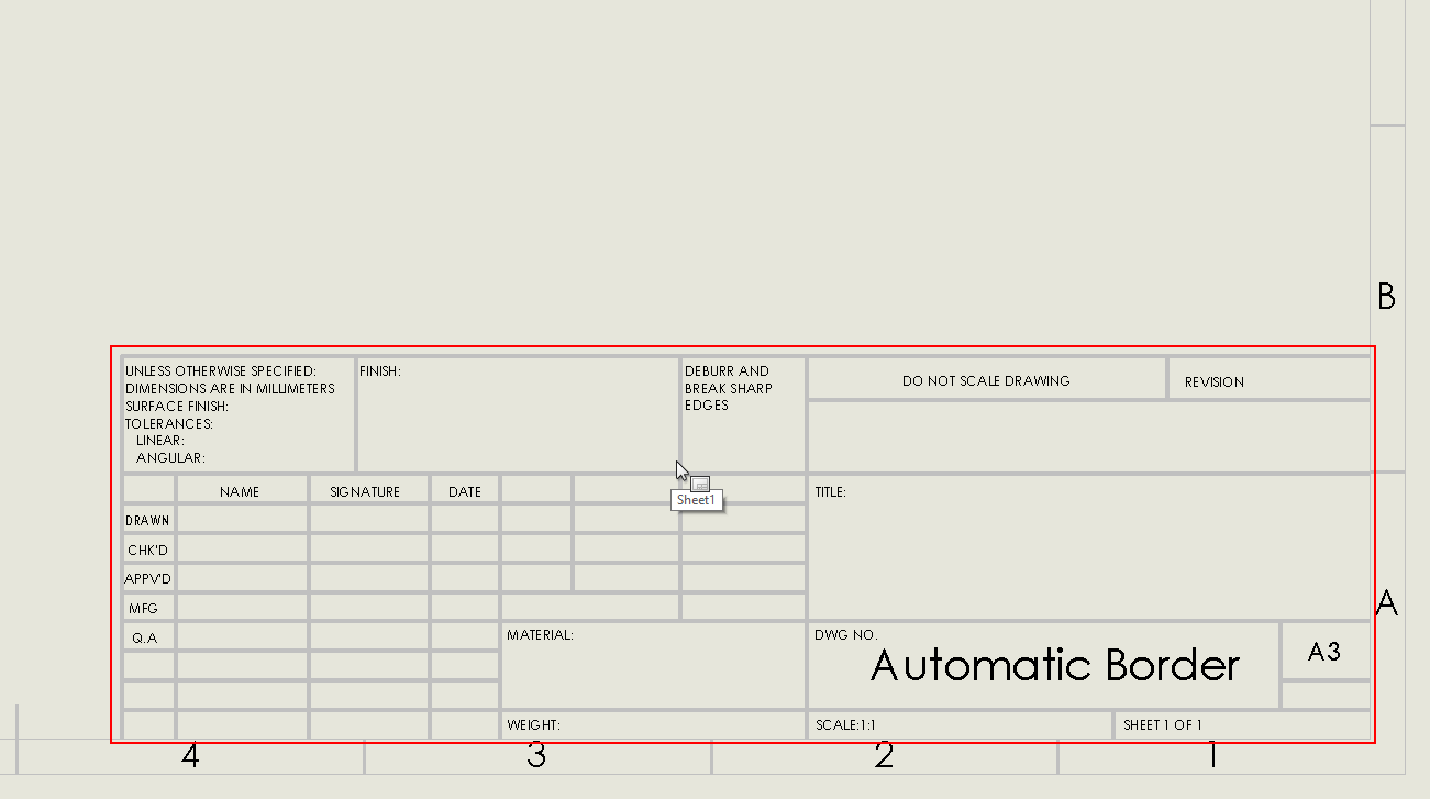
The Title Block
Usually positioned in the bottom right hand corner of your sheet and contains key information such as Part number, Description, Material, etc.
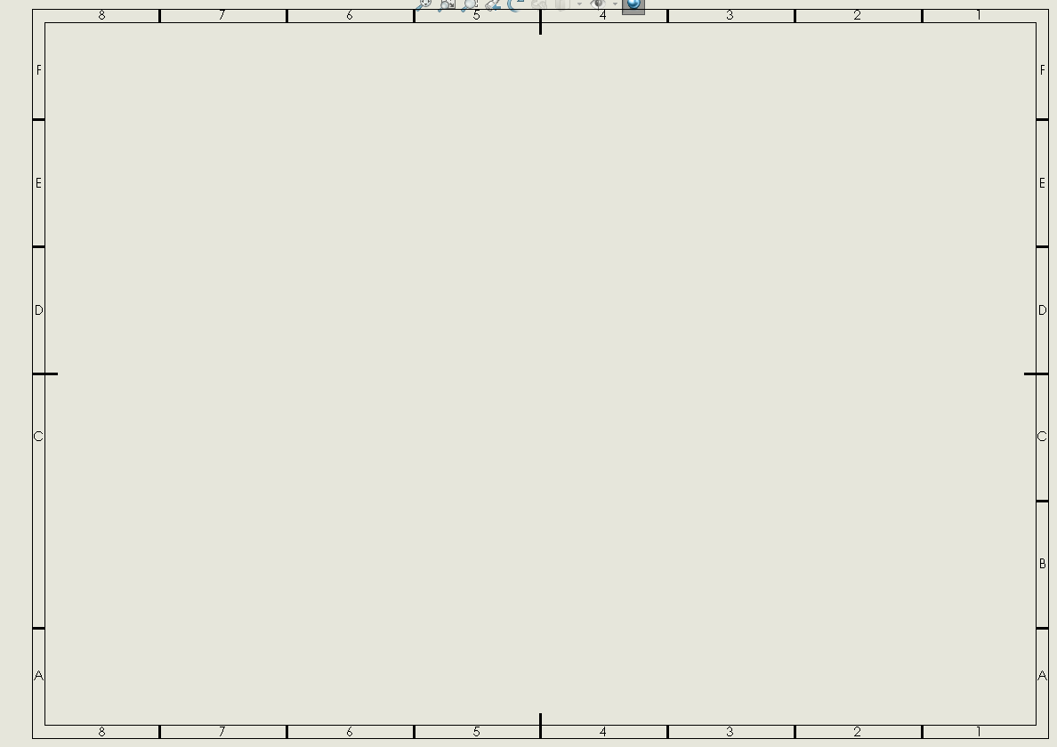
The Border
As the name suggests, this outlines your entire drawing sheet. It usually has rows and columns as seen below.
How the Automatic Border tool works
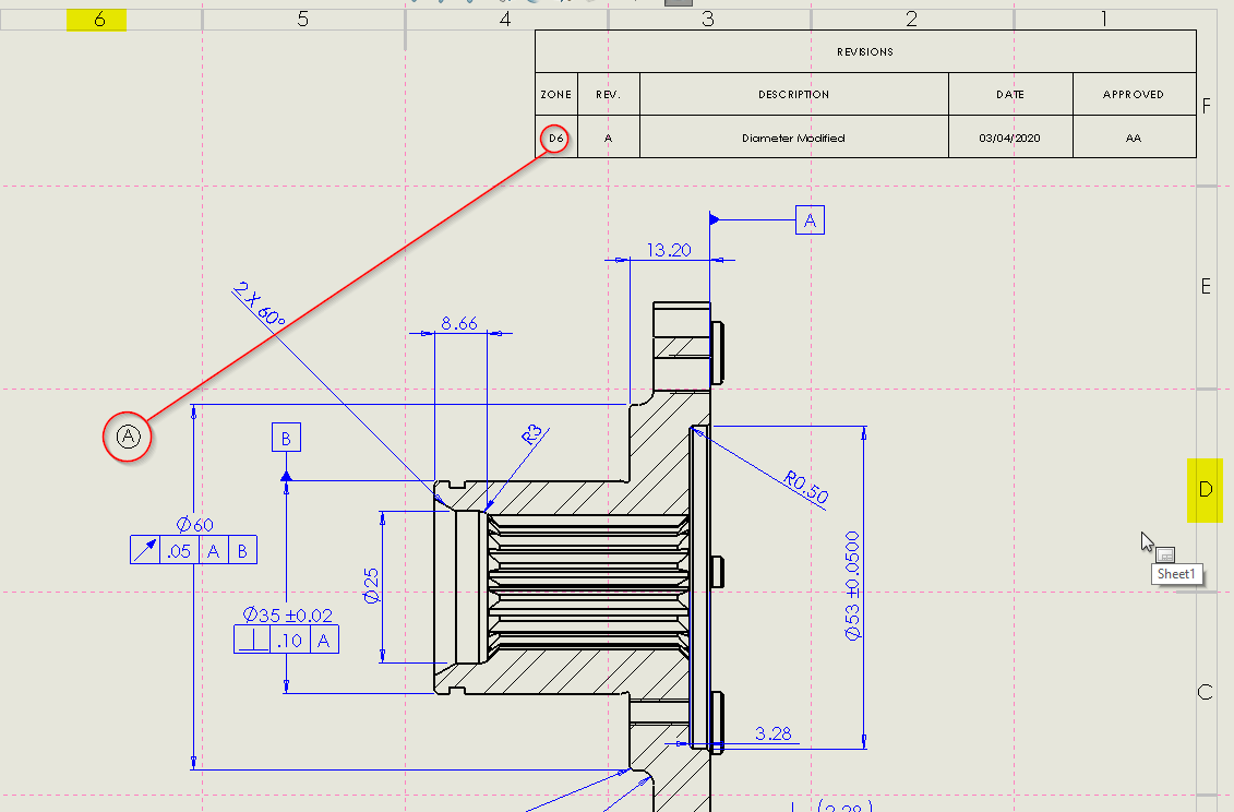
Historically-speaking, your drawing borders have been made using normal sketch entities, such as lines, rectangles & annotations. This means that if you wanted to modify your borders, by adding additional rows, column or modify your margins in some way, it was a bit tricky & time consuming. This is not the case with the automatic border tool. The process is simple and we have the added benefit of it automatically linking to zone lines. So, if you create a revision balloon the zone reference will be created for you automatically.
You will find the automatic border tool on the sheet format toolbar.
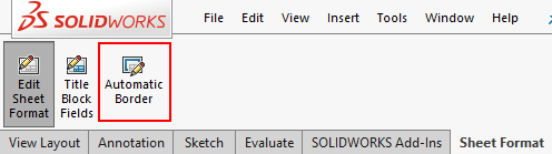
Before you can use the tool, you must be in edit sheet format mode.
Upon launching the automatic border tool you will be prompted to delete out any entities that are no longer required, i.e. the lines & entities that make up the old border.
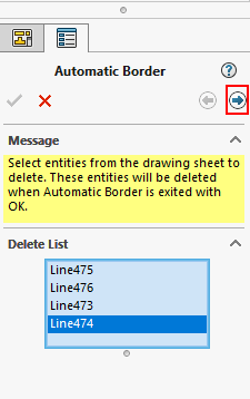
Once you have selected those entities, click on the arrow at the top of the property manager (highlighted above).
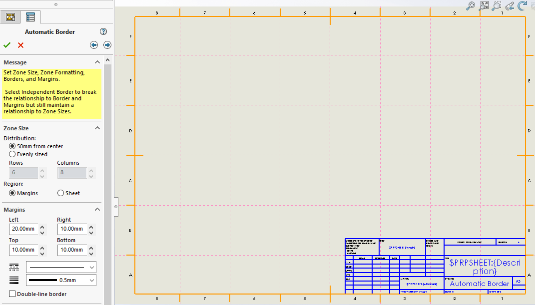
At this point you will see a preview of the border within the graphics area and several controls within the property manager. We’ll run through those commands below.
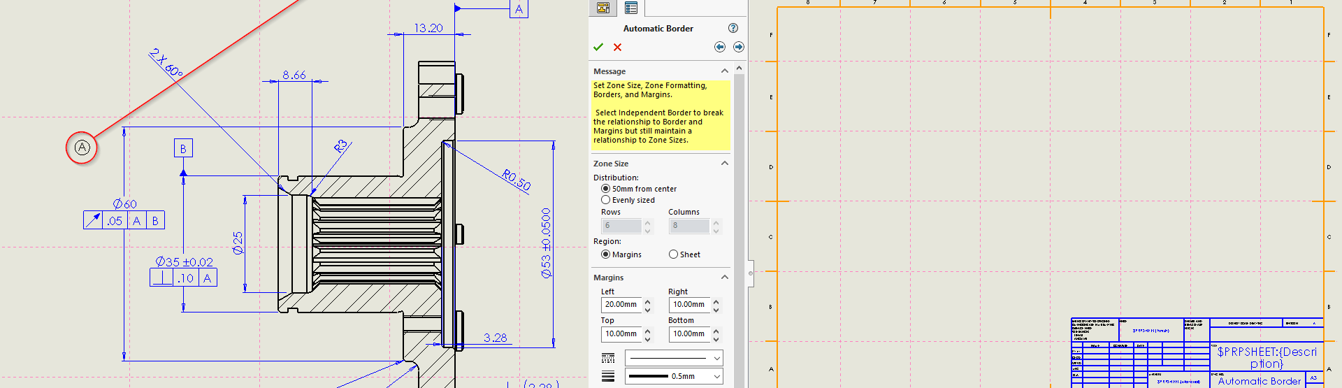
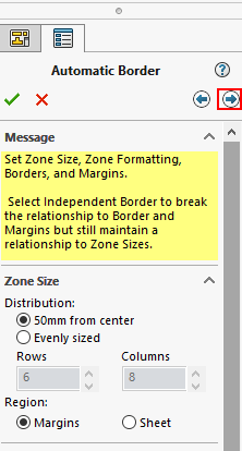
Zone Size
This allows us to control Column width & Row height
You can choose to have your columns and rows either spaced at 50mm from center (this means that the number of rows and columns will be driven)
Or you can select evenly sized. The number columns and rows will become active for you to modify and the system will automatically sub divide the border equally.
Margins
Allow you to control to define the distance from the top, bottom, left, and right of the sheet to the border.
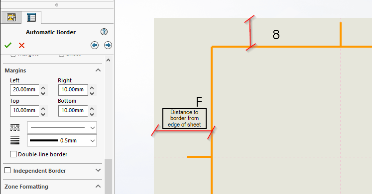
We can also define the line style and width, and we can have a single-line or double-line border here too.
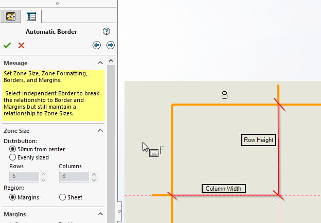
Independent Border
Breaks the relationship between the border and margins but still maintains a relationship to zone sizes
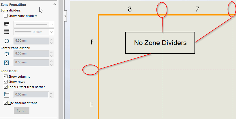
Zone Formatting
Here we can choose whether to show zone dividers or not.
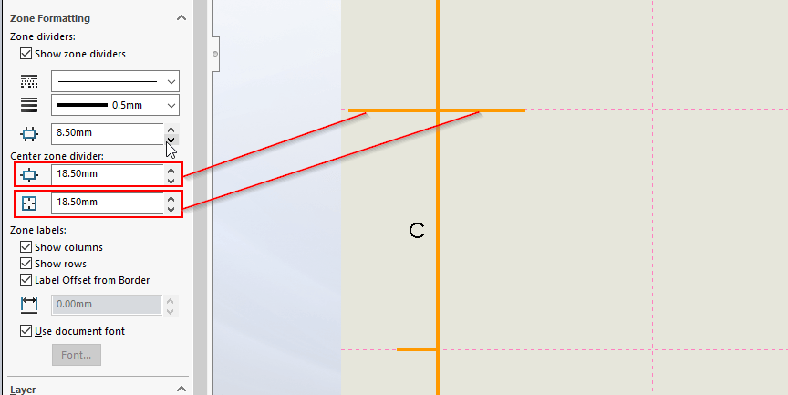
What line style & thickness we wish to use for the dividers
Inner & outer length of centre zone divider
Show zone labels for Columns & Rows
Define label offset position
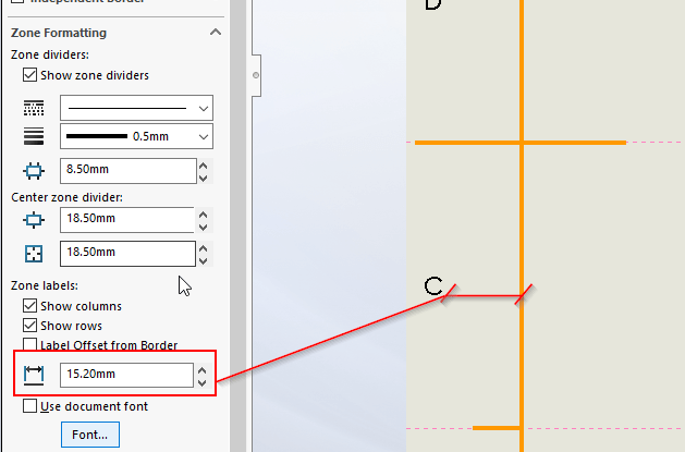
Font type & size used for labels.
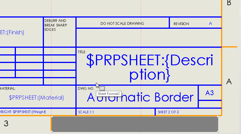
Once happy, Click on the arrow in the top right of the property manager, this will allow you to create a margin mask.
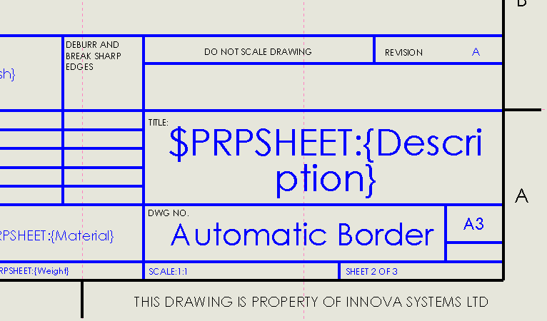
A margin mask will allow you to create a mask that hides the zone dividers and labels. One use for this would be when you have a note on the outside of your drawing border (as per the below image).
To add a margin mask, click on the ‘add’ button and resize it by dragging the handles. You can have as many masks as you like.
Once you are happy with your border, its worth making sure your titleblock sits nicely within it. Its possible for you to create relationships between sketch entities within your title block and the 4 internal corners of your border.
When everything is correct, exit sheet format & save your document away as a template. Templates should be saved in the folder defined as document templates within your system options.
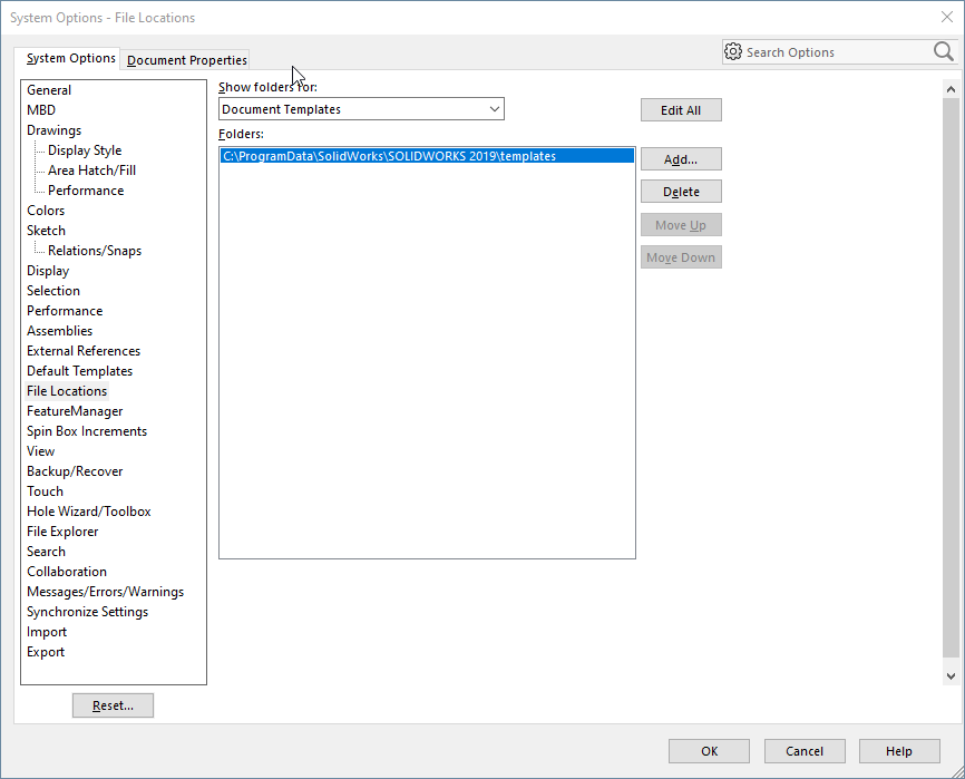
Just remember to save your sheet format away in the correct location, this is also defined under file locations, sheet format folder.


