
How to do it the old way (Pre-2014)
A weldment profile is basically a sketch containing closed contours. For example, a sketch of just a square will generate a weldment profile of a solid square piece of geometry. If the weldment is required to be hollow, the sketch needs to be changed accordingly. The limitation of creating weldment profiles is much the same as the sweep feature – as long as the sketch is closed, the possibilities are endless! Even multi-body weldment profiles can be created.
It is important to understand the windows file structure of weldment profiles, they have to be placed within a number of folders. When creating custom profiles the first folder should be the “Standard”, the second (within the first), the “Type” and in the type folder the file name “Size” should be located.
How to do it now – Configurable profiles!
As of the release of SOLIDWORKS 2014, an alternative, more efficient method of creating what is known as “configurable custom weldment profiles” has been made available.
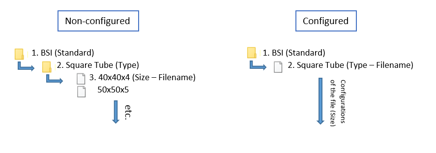
This technique is fairly similar to the previous one, the main difference being file structure. Instead the file is saved as the style of the weldment i.e. “Square tube” and configurations within that part dictate the various sizes, eliminating the need for so many files. See the below image for a clearer understanding of the file structure difference between the two techniques.
Benefits
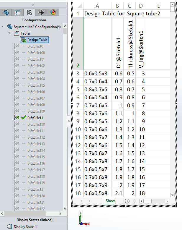
The benefits of this enhancement are many. Due to the use of configurations to create various sizes, a design table can be used to create a vast amount of sizes very swiftly, saving large amounts of time by generating and manipulating multiple sizes simultaneously. Unlimited configurations can be created at once using this method. See the image below for an example of a design table. Note that custom properties, sketch points and dimensions are carried through all configurations so they only have to be set once! Also as of 2016, the size list is arranged alpha-numerically (smallest at the top), with an additional sub section at the top displaying the most commonly used profile for quicker selection. So it is not important what order they are created in the design table.
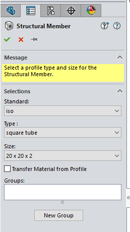
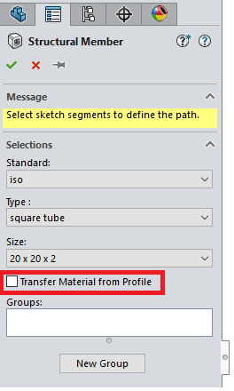
The following image is what you’ll see when using a configurable profile as a structural member. Note the suffix after Type (“- Configured Profile”) is used to illustrate that the profile that is being used is configured. Also please note the location of the file is only ‘buried’ one folder deep unlike the non-configured technique.

File type
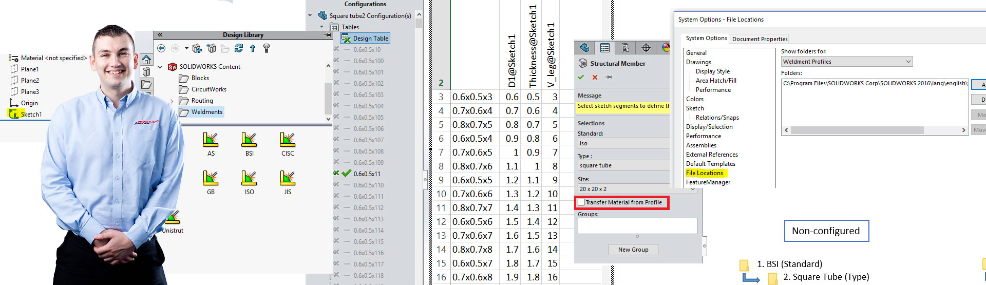
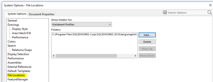
In order for the profile to be recognised as a library part, it needs to be saved as a .sldlfp within the relevant location. This location can be anywhere the user wants, even on a shared drive if necessary. As long as the profile is ‘buried’ as described earlier and SOLIDWORKS is pointed to the correct location then this will be fine. The file location for weldment profiles can be edited as shown in the below image, via:
Tools > Options > System Options > File locations > Weldment Profiles > Add
Add to Library
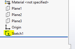
After the file has been saved in the correct location as the correct type, it needs to be added to the library in order to be used. To do this all the user needs to do is right click on the sketch and select add to library. When this has been done, a small ‘L’ will appear next to the sketch as shown in the image below.
Additional profiles?
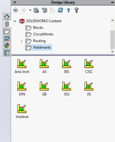
SOLIDWORKS provides a few profiles as part of the install. If the user requires anything other than what is included under type, then this has to be created manually. Alternatively SOLIDWORKS also provides the availability of additional profiles within standards on the task pane under SOLIDWORKS content, as shown in the below image. To include these additional profiles, the user must hold the control button and left click on the relevant standard, then select a location to save the file. This will then need to be extracted to the correct location as described above. Note that these are non-configurable profiles.
Transfer material
SOLIDWORKS 2016 brings with it a great enhancement to the use of weldments. It gives the user the ability to transfer the material properties that have been specified within the weldment profile when using it as a structural member, as seen in the image below. These can be configures too if using configurable weldment profiles. This is a great time saver and can still be edited later if necessary.
We hope you found that useful!
Have you seen our blog archive where we have posted plenty of helpful articles? We also have a fantastic video library filled with easy-to-follow videos on a number of topics inspired by other SOLIDWORKS users – take a look.
Also, don’t forget to follow us on twitter for daily bite size SOLIDWORKS tips, tricks and videos.


