
Customised templates are most commonly used for a drawing, where such things as company logos, names, dates and other custom properties need to be remembered. Ideally other custom templates such as part and assembly need to be created in addition to the drawing to be able to pull such properties through.
Follow the steps below in order to create your own custom templates…
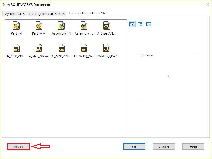
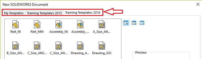
By default, a template for each file type; part, assembly and drawing, will be included within the installation. As seen in the images below, you have two view options when selecting a template; ‘novice’ or ‘advanced’. The advanced option is especially handy when you have more than one type of file template.
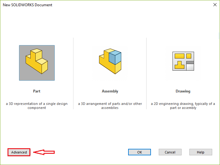
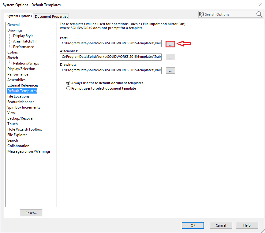
If the file type is selected as per the novice view, the ‘default’ template will be selected. This can be altered via; Tools>Options>System Options>Default Templates as seen in Image 3.
Part & Assembly template
The first step to create your own custom part or assembly template is to open an existing one. It is important to note that any changes done within this template will remain when saving as a new template. For example showing planes, drawing sketches and even zooming in and out will make a difference.
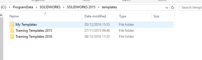
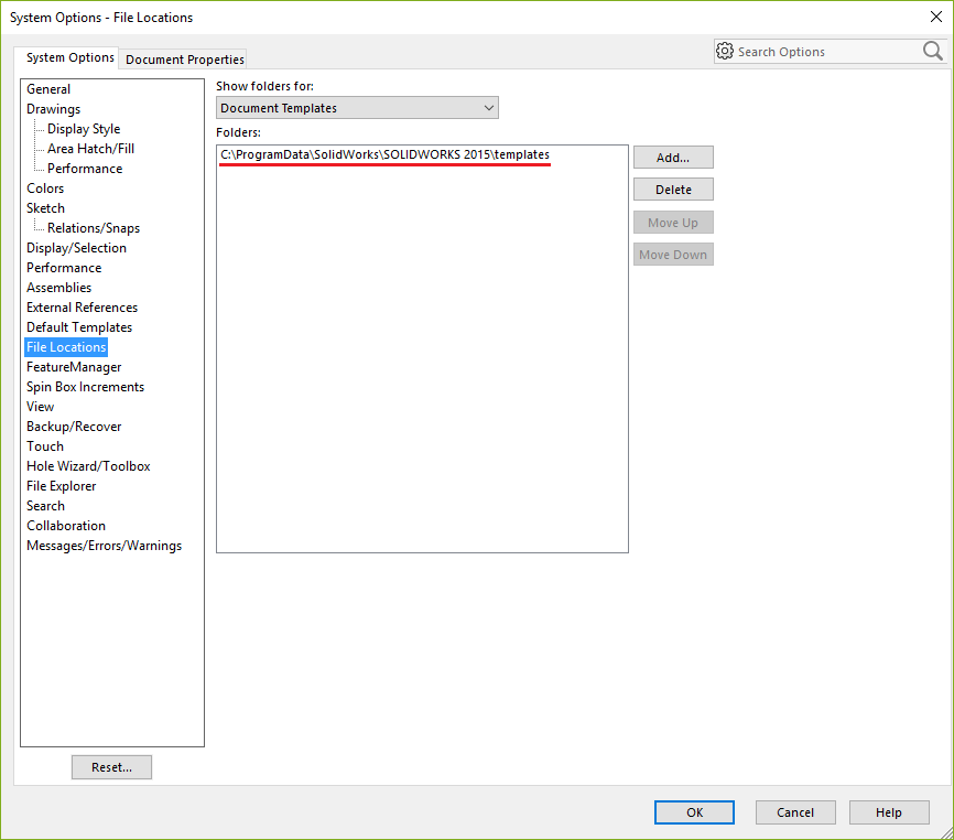
When you have finished creating it, ensure that you save the file as a .PRTDOT or .ASMDOT format as required. The location of this file needs to be in a location that SOLIDWORKS is ‘looking’. This can be checked via; Tools>Options>System Options>File Locations>Document Templates, as seen in Image 5. Any folder created in this location is then seen as a new tab within the advanced template view as seen in Image 4.
Tip: Ensure that you choose the file type before you choose the file location.
Drawing template
The creation of a drawing template is a slightly different process. Firstly it is important to understand that a drawing template is constructed of two files; the sheet format and the drawing sheet. The drawing sheet contains the drawing views, sheet size, annotations and dimensions, and the sheet format contains the border, text and the title block. These together comprise the drawing template.

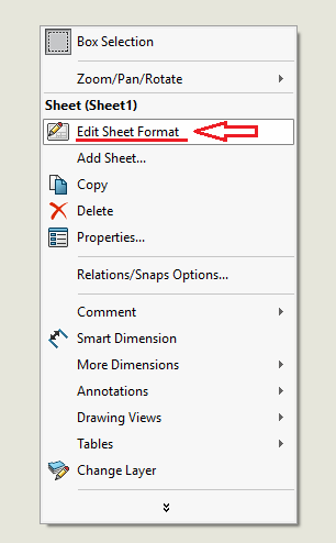
The first step is the same as the procedure for a part and assembly template. Open an existing drawing template, choose the size of the sheet, the units, the projection type, etc. Then access the sheet format which can be altered via the right-mouse-button on the sheet under the command “Edit sheet format” as seen in Image 7. This then enables you to customise the border, title block and add a company logo for example. Most importantly it enables you to link properties from the drawing to the associated model to enable them to update parametrically.
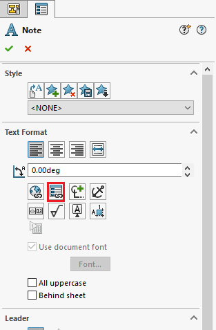
In order to do this a note needs to be inserted from the annotations tab on the CommandManager. When the note is selected the PropertyManager will populate itself and the command “Link to Property” as shown in Image 8 needs to be selected. This provides the ability to either link to a property within the drawing file (current document) or within the part/assembly file that is referenced within one of the views within the drawing (Model found here). Hence the need to set up part and assembly templates as well.
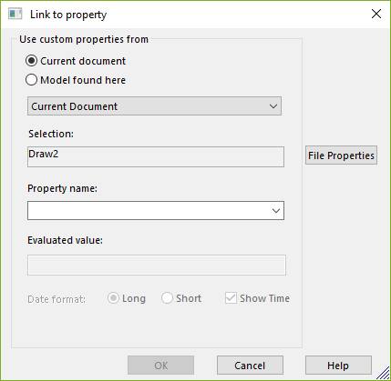
You can either use the drop down list to choose properties that are already set up by SOLIDWORKS. Alternatively you can access the file properties via the command on the right hand side. This is the same window as accessed via; File>Properties or the icon as depicted in Image 10.
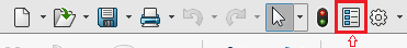
Tip: File properties can also be accessed via a keyboard shortcut (Ctrl & Spacebar).
Within this window you can then either create a new property or select an existing one from either the drawing or the model file if it has been created.
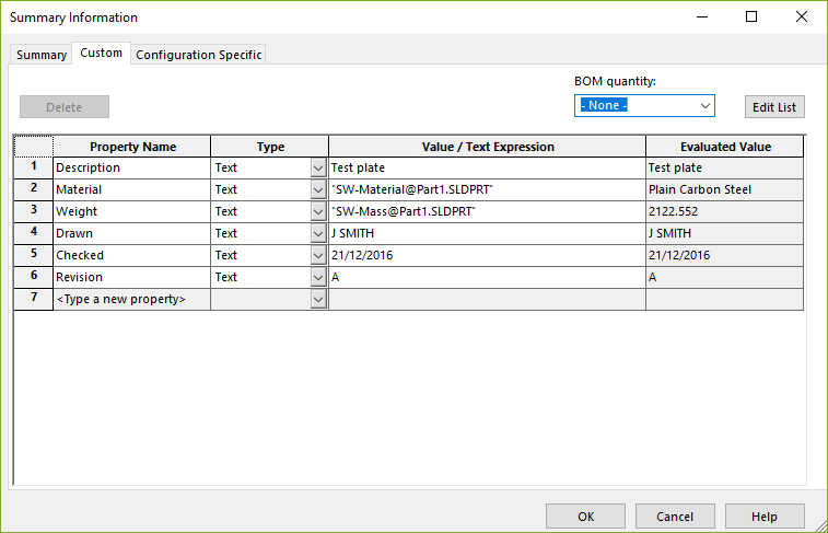
Image 11 shows an example of a list of some typical properties within a part file. As you can see some of these have been linked to a SW property. The property “Material” is linked to the actual material as applied by the user. This will then enable a direct link between editing the material and the drawing updating, rather than the user manually changing anything.
Once finished, saving is a two stage process. Firstly, the sheet format needs saving via; File>Save Sheet Format…
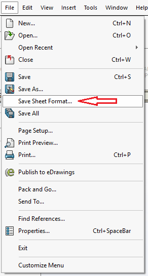
…next, save the drawing template as a .DRWDOT file format as discussed earlier and you’re done!
We hope you found that useful!
Have you seen our blog archive where we have posted plenty of helpful articles? We also have a fantastic video library filled with easy-to-follow videos on a number of topics inspired by other SOLIDWORKS users – take a look.
Also, don’t forget to follow us on twitter for daily bite size SOLIDWORKS tips, tricks and videos.


