Unlike the manufacturing industry, construction lags behind in its adoption of digital technology, Design for Manufacture and Assembly (DFMA), componentised design and modern methods of manufacture. In response, Innova Systems customer, Samuel Bromley, founded Element Design Ltd, a company that specialises in fabrication-ready industrialised DFMA for the built environment. In this guest blog post, Samuel shares his insight on Building Information Modelling (BIM), transferable industrial designer skills, and why SOLIDWORKS 3D CAD should not be overlooked by the Architecture, Engineering and Construction (AEC) industry.
Fabrication DFMA design for the AEC industry
The environmental impact of the construction industry through material and energy consumption is incomparable to other manufacturing sectors. Responsibility & accountability for AEC design and engineering projects should arguably impart more consideration than any other production industry. Big picture early-stage design decisions and the use of correct digital tools make significant differences to the final product’s embodied carbon and in-use emissions but it’s important to choose the right tool and experience for the job.
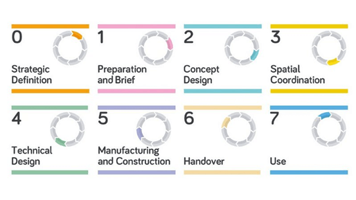
UK AEC project workflows are directed by the RIBA Plan Of Work, a linear staged process outlining project strategy, management, design, manufacturing & construction. More recent amendments to the process have included reactions to the ever-increasing digital workflows adopted by architectural and engineering companies, in an effort to improve process efficiencies and offer greater value to clients. As AEC firms become increasingly vertical in design, manufacturing & construction integration there has been an uplift in the need for skills and experience offered more traditionally from industrial & mechanical design engineers; including proficiencies in design software typically associated with automotive, mechanical and product design such as SOLIDWORKS.
With the right software and industrial design experience, using SOLIDWORKS for BIM on RIBA stage 4 ‘Technical Design’ delivers on achieving architectural design intent whilst considering upstream fabrication and construction challenges that other CAD packages can’t manage.
SOLIDWORKS in AEC design
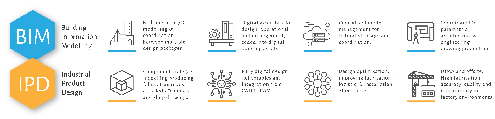
It’s important to recognise that BIM is a modelling and data workflow methodology – not a specific suite or brand of software. BIM is a broad requirement of 3D modelling practices in relation to the stages of design, engineering and construction for buildings, infrastructure and civil projects, enabling coordination and collaboration between multiple disciplines of the AEC industry.
The risk of being convinced to use “BIM” labelled software for advanced detailed design and modelling tasks is that you soon find yourself locked in, using systems that cannot produce specific tasks and deliverables in the most effective manner. It can’t be argued that software packages such as Revit and ArchiCAD are unique in the ‘building scale’ CAD offering (this is their value), but they aren’t suited to the ‘product scale’ needed for the development and production of fabrication ready DFMA information.
During technical design stages, the necessity for BIM compliant, parametric modelling capable of producing fine architectural detailing can only be fulfilled with tools made for engineers. For this type of work, CAD packages made specifically for industrial design engineers put the right tool in the right hands, and SOLIDWORKS has been the right choice for Element Design.
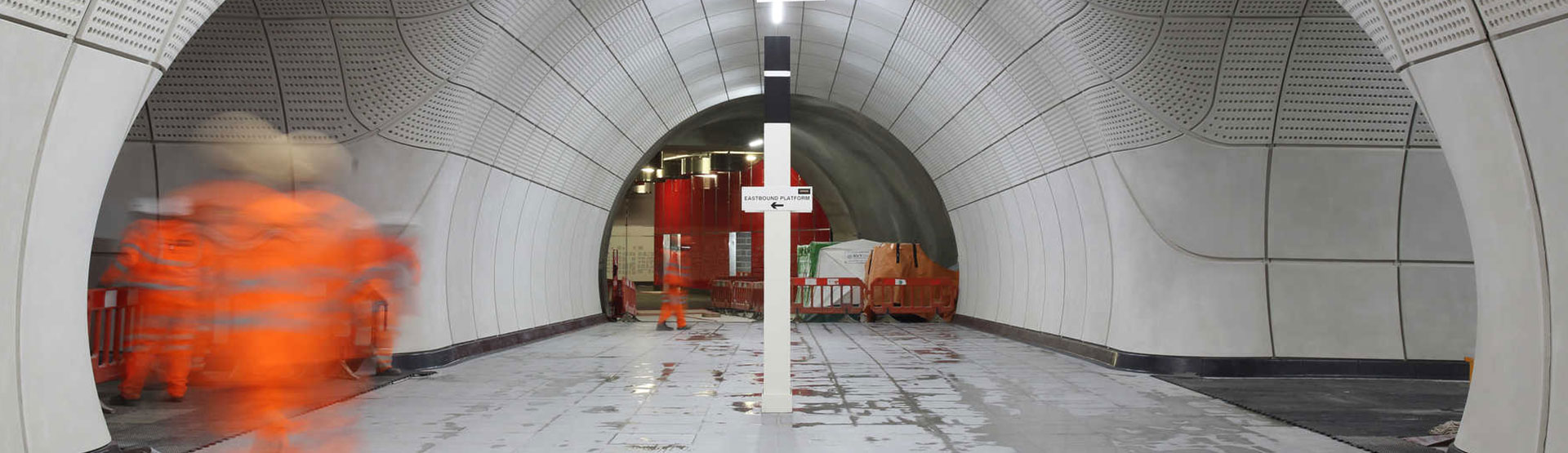
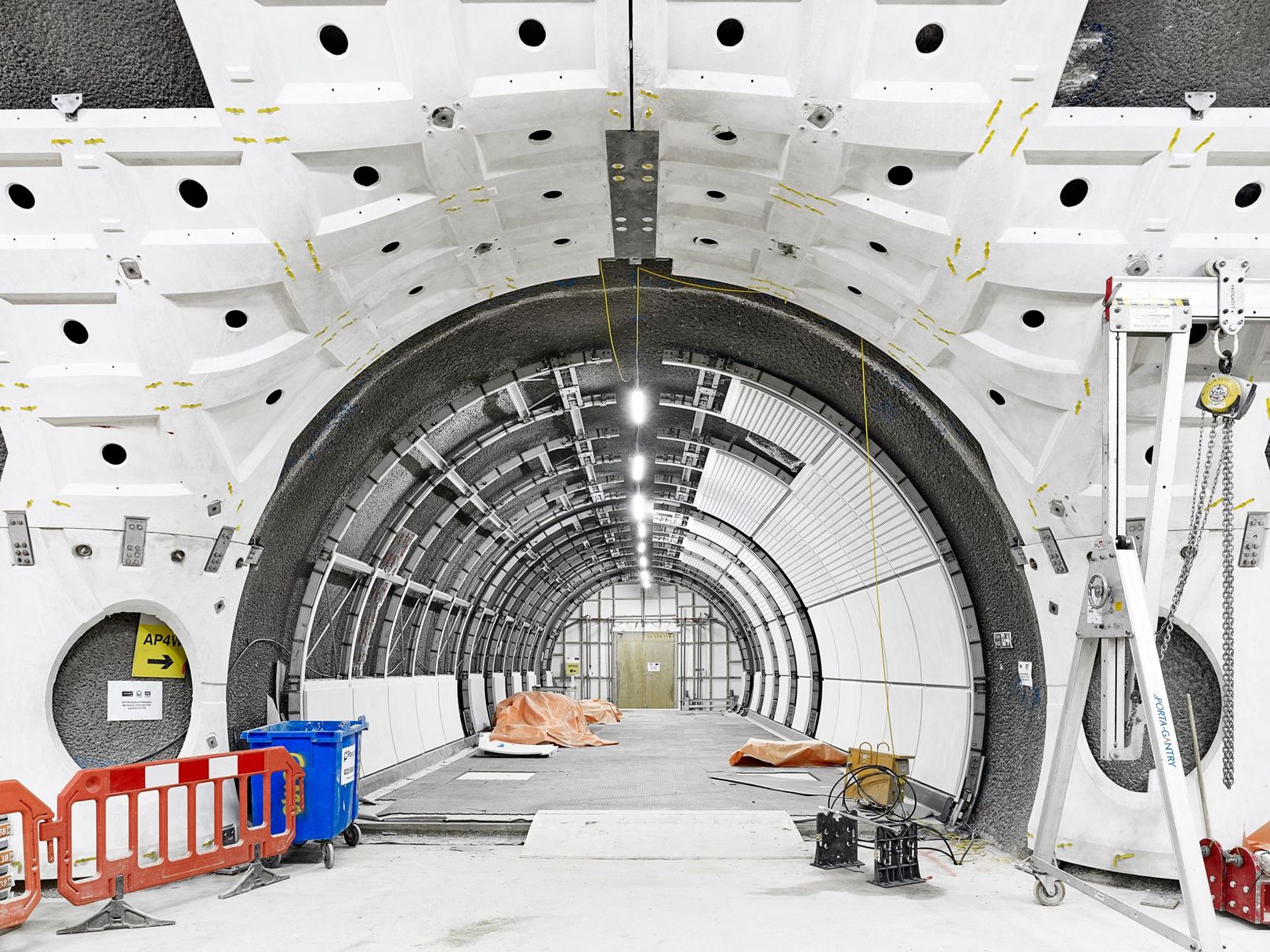
SOLIDWORKS was successfully used for RIBA stage 4 workflows on large infrastructure projects including Crossrail & Northern Line Extension (Credit; Bryden Wood), and traditional residential and commercial projects adopting ‘Modular Integrated Construction’ (MiC). Project manufacturing partners also used SOLIDWORKS, resulting in fully integrated workflows as native files can be exchanged between companies without the use of interchangeable file formats, which reduce geometry fidelity and lose metadata. These projects benefited from the BIM compliant capabilities and advanced parametric modelling functions of SOLIDWORKS, reducing change risk and improving design to manufacturing information exchange.
SOLIDWORKS for an AEC workflow
Typically, a RIBA stage 2 or 3 design (concept or developed) would be received from the architect. Depending on the project, this could be in native Revit, Rhino or a similar 3D format providing architectural intent. To ensure intent is achieved, the 3D data is imported into SOLIDWORKS using 3D Interconnect to maintain a live link with the interchangeable 3D data.
SOLIDWORKS is used to model highly accurate geometry, incorporating considered manufacturing detailing such as drafts for de-moulding pre-cast and glass reinforced concrete panels, or weld and bend details on structural steel components.
Metadata is coded into the productised designs, fulfilling BIM level 2 asset data requirements. This data is used downstream for procurement, manufacturing, logistical track and trace, and later life access and maintenance information.
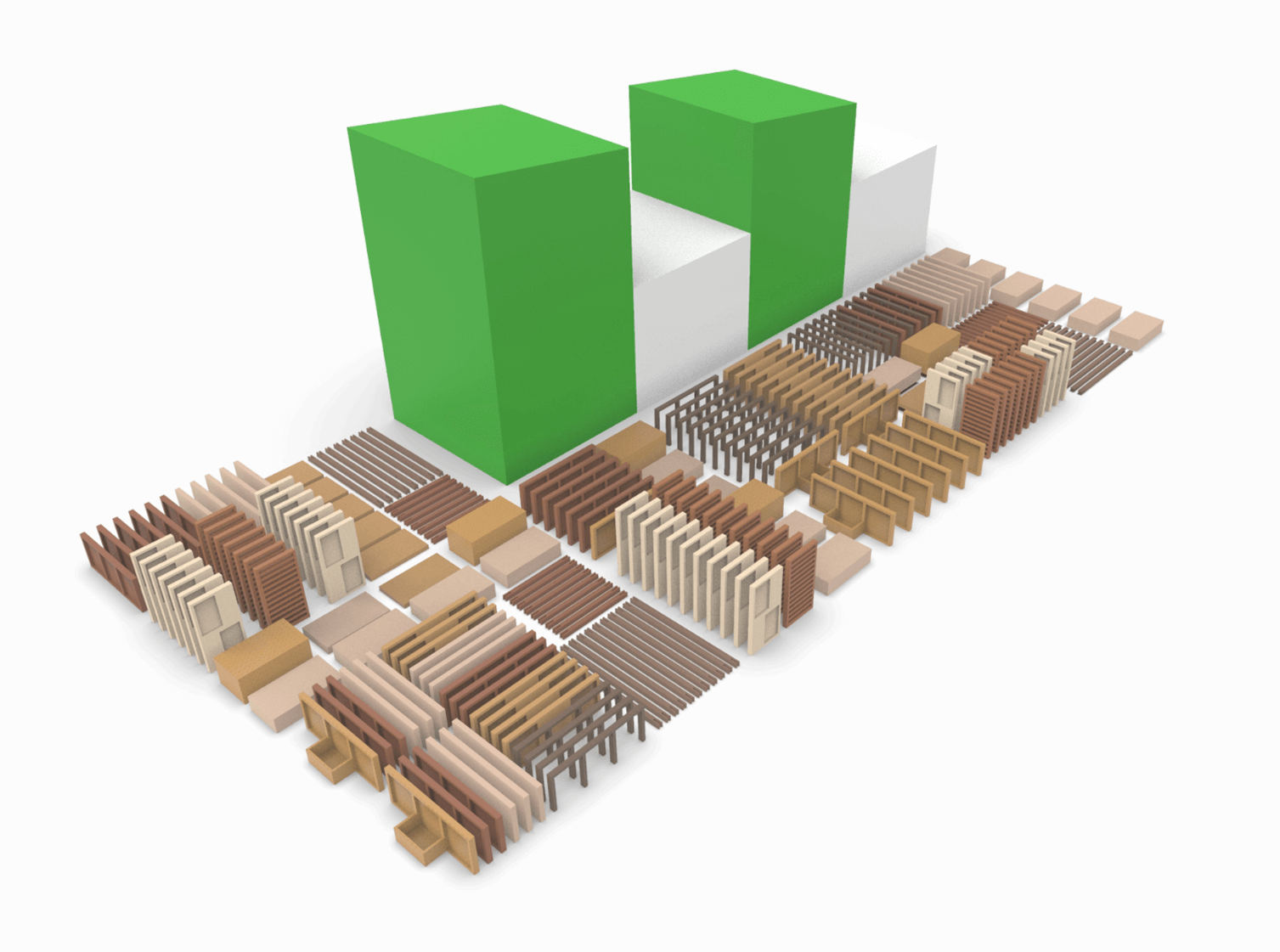
One of the most important stages of the process is considering how the product is split into sub-assemblies to aid with manufacturing, procurement, delivery and installation. Controlling this through SOLIDWORKS’ ability to manage assemblies used multiple times on one project is as simple as it should be. It is fair to say that other BIM focused packages struggle with this control and adaptability.
QA in large construction projects requires vast coordination with multiple design packages from varied sources. Reviewing 3D design data provides perspective that is hard to replicate with a 2D drawing review. Exporting interchangeable file formats in real-world coordinates allows information from multiple design packages to be reviewed quickly in specialist coordination and clash detection software.
Fabrication shop drawings are produced natively in SOLIDWORKS. Annotations and dimensions linked to geometry are automatically updated to reflect changes, reducing risk of re-work from changes that often occur during development upstream.
Client BIM compliance often requires completed developed designs to be exported back into the agreed federated modelling package (most likely Revit) and no native interoperability exists between packages. Therefore, depending on master model software, typical IFC, STEP or IGES formats that can be saved from SOLIDWORKS are best. However, exchange of metadata will be lost as there is no true function to transfer. Third party companies such as CAD exchanger or BIMDex have proven to be the best way to transfer files with data, but there are often limitations with configuration-specific properties.
Engagement through BIM & Industrial Product Design
The linear RIBA Plan Of Work encourages a single direction, downstream transfer of information. Larger multi-disciplinary firms benefit from engaging in several stages of this process. For firms and specialists responsible for smaller portions of design, the transfer or receipt of design package information is more likely. Information exchange risks unintended interpretation, or is subject to limitations and rules of operation and manufacturing too late to be addressed. By the time this information is received, it has passed through multiple approval process and is unlikely to be optimised, rationalised or considered for design and manufacturing preferences of the now responsible companies.
Early-stage engagement between design stakeholders with fabricators and installers addresses opportunities that are missed by the linear route. Element Design position itself as the enabler of this engagement as specialists in DFMA industrial design, appreciation of architectural intent, construction methods and digital communication. The most effective communication is with detailed 3D models that do not hide the reality of fabrication and manufacturing methods with draft quality, but instead bare all for review and comment during work in progress.
About the author
Element Design’s, Samuel Bromley, is an experienced industrial designer who has used SOLIDWORKS since 2006. His experience in the AEC industry was earned whilst working as a Director in the systemisation department for London based architects and engineers, Bryden Wood. He was design lead responsible for architectural and structural packages including Crossrail and Northern Line Extension, HK Advanced Manufacturing Centre, Kowloon Lyric Theatre, HKIA & GFRC cladding projects.
Experienced with modular integrated construction and productised design for commercial, infrastructure and residential projects, Samuel was involved in developing repetitive & re-deployable construction systems (P-DFMA). Samuel specialises in process engineering, complex architectural geometry, façades, bespoke construction systems and digital delivery of ‘ready for fabrication’ deliverables.
Element Design’s clients include a modular housing developer constructing affordable housing in West Africa and ECOs working to decarbonise the energy and heat network.
For more information, Visit the Element Design website here.