

We had a call from a customer the other day regarding cross hatching. There were a couple of things that he wanted to do, which at first I did not think were possible. After a bit of research and head scratching, I managed to come up with a solution. Maybe you’ve come across the same problem and will find the following cross hatch tutorial useful.
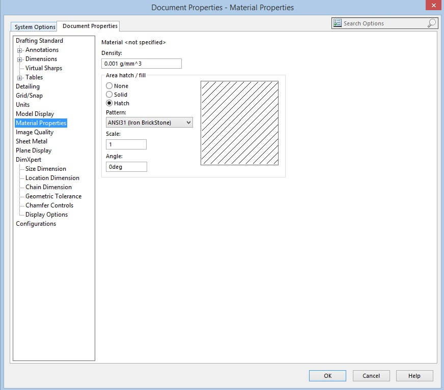
If you apply a material to a component – and then section that component – the default cross hatch for that material is applied to it. If you have no material applied, a default cross hatch is applied. This is controlled from the PART document property settings shown below.
This particular customer creates furniture, and only wants to cross hatch certain components, not all of them – and would also like a specific wood cross hatch, which does not currently exist.
So, let’s look at the specific wood cross hatch first.
A file exists within the installation directory for the version of SOLIDWORKS you are using (C:\Program Files\SOLIDWORKS Corp\SOLIDWORKS\Lang\English) called sldwks.ptn which is where the information for the standard cross hatch available is read from. If you open this file with notepad, it gives some instruction at the header of the file on how to create your own custom cross hatches. Very useful. It is advised that you take a copy of the original and keep it untouched, just in case the modifications cause any issues.
I have copied the header instructions of the file below for reference:
Each hatch pattern starts with a ‘*’ character followed by a ‘:’ and an ID. And again followed by a ‘:’ This is the numeric identifier for the hatch pattern. Please Note: SOLIDWORKS reserves numeric identifiers in the range of 001 to 500. User defined hatch patterns should start with 501
How to read this table:
Each non-empty line that starts with a semicolon ‘;’ is a comment. Otherwise, the line could only be the pattern’s header line that starts with an asterisk ‘*’ immediately followed by the name of the pattern, per the rule mentioned above.
All non-empty non-comment lines after the header (before the next header or until end-of-file) must be data lines that conform to the format described below.
Each line corresponds to a subpattern which consists of one bunch of parallel uniformly interspaced graphical lines with the same linear pattern on each of them (or all have no pattern i.e. to be drawn as solid lines)
The data line contains data separated by commas
First is the angle at which the lines are drawn, the second and third are the 2d coordinates of the point which is the start of the subpattern (start of the linear pattern on one of the lines) The fourth is the offset for the start of the linear pattern between two consecutive lines of the subpattern, the fifth is the spacing between the lines
The subsequent data items describe the linear pattern. They are optional, their number is arbitrary or they might not be there at all. If they are absent, the line does not have a pattern. Else, the items have the following meaning:
- if it is positive, it is the length of the visible dash of the line
- if it is negative, it is the length of the empty segment of the linear pattern
- if it is zero, a dot should be placed there
- The requirements do not restrict the syntax of the data line, per the following:
- There must be an even number of optional data
- Every other number (all odd-numbered or all even-numbered) must be negative (hence, the other half of them must all be non-negative i.e. positive or zero
Take notice that the spacing is placed on the fifth rather than the second line, as only the angle and the spacing are truly mandatory data. For linear pattern offsets, the datum should start the optional data and thus there should be at least three optional data items 9of less than three, errors will arise) the start of the pattern may be unimportant when there is only one subpattern of the pattern, and especially when the lines of that subpattern have no pattern. Thus, the coordinates should have been placed at the third and fourth rather than the second and third as currently set.
There are a couple of things to remember. Each cross hatch has a number, and SOLIDWORKS has reserved the first 500, so any custom cross hatch you add must start like so *:501:Wood,
“501” being the unique number and “Wood” being the name you want to appear in the dropdown list. The entry also needs to start with a *
I found the following website (and I’m sure there are a few more!) which had a number of AutoCAD .PTN files available for free to download: http://www.cadhatch.com/#/autocad-wood-hatch-patterns/4555347745
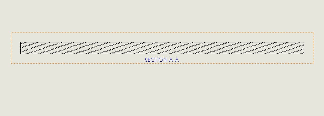
You can then just open the file in notepad, and copy the contents into the SOLIDWORKS .PTN file – your own custom wood grain hatch pattern!
I also noticed on the forums, that depending on the complexity of the pattern, it may not work. There seems to be an unpublished limit of the number of lines that you can add to this file – so just be aware that the more complicated patterns may not work.
With the ability to create your own custom materials in SOLIDWORKS, and this functionality – you can apply custom cross hatching to your custom materials and build up a bespoke library.
So, the other part of this. How do we make it so that, by default, a component does not cross hatch when we section it? Because the default cross hatch is set in the part file – we can open the part template and then change it to “none” within the options (shown previously), then re-save the template. Any new components we make, when cross sectioned, will not have a cross hatch. We could then only apply materials to what we wanted to cross hatch – and save ourselves a fair amount of time in the drawing.
Equally, because no component is cross hatched, you could use the area/hatch fill tool within drawings to manually add your cross hatching.


