
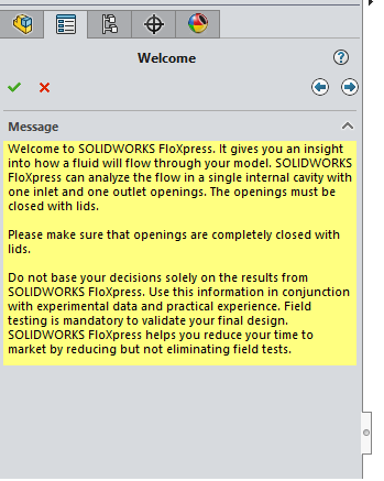
Every SOLIDWORKS version provides the ability to run basic internal flow analyses of geometry using the FloXpress tool. As long as your model has one inlet, one outlet and one internal cavity this can be achieved. For more information on activation, please see our Activating and using SimulationXpress blog post. Once activated, a wizard guides you through each step in the study process.
Step 1 – Check your geometry:
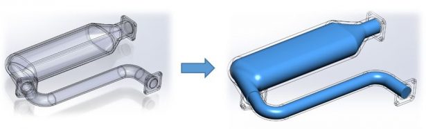
The first step within the study is to ensure that the model is watertight, so that no leaks occur. The study will not run if the fluid is able to escape the internal cavity! The best way to do this is to create geometry over the openings, ensuring that they do not affect the internal cavity as much as possible. These are known as “Lids”.
Tip: Avoid corner to corner geometry when closing the openings as this will result in an invalid contact and will not seal the cavity properly!
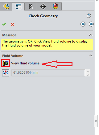
Once this has been achieved, you can select “View fluid volume” as seen in Image 2 which enables you to ensure that your model has been sealed and the fluid volume represents the correct internal cavity. Below this selection is the smallest flow passage within the model, which is automatically calculated, but can be manually adjusted if necessary.
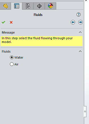
Step 2 – Fluids:
The next step in the study is to choose which fluid you would like to flow through the model. As can be seen in Image 5, you have a choice of two; water or air.
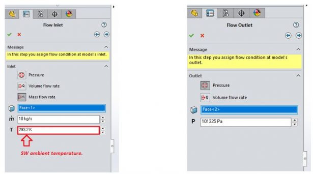
Step 3 – Inlet & Outlet flow conditions:
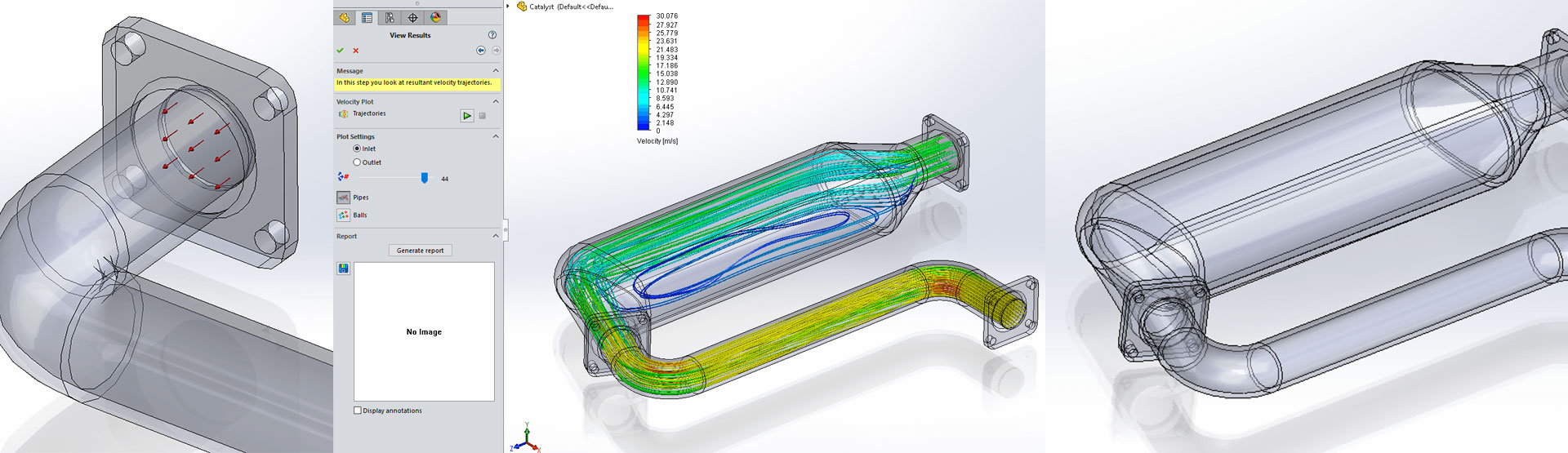
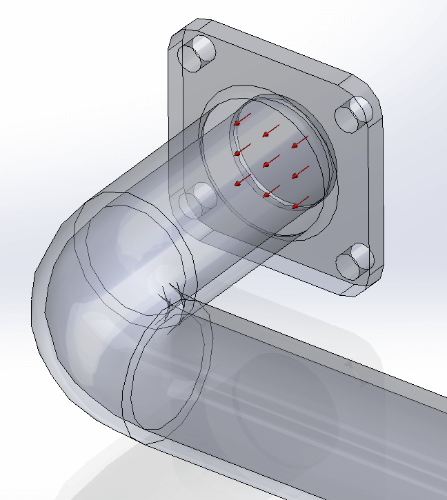
Next, both inlet and outlet flow conditions need to be defined. For both of these selections the internal faces of the lids are chosen respectively. The flow condition also needs to be defined for each of the openings, including the temperature of the fluid, by default this will be set to the SOLIDWORKS ambient value (293.2K/20.05°c). A graphical representation of the style of flow is then illustrated, as seen in image 8.
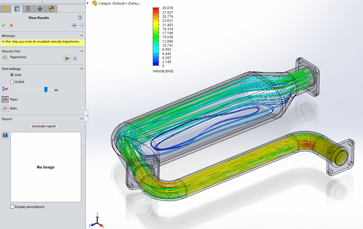
Step 4 – Solve & View Results:
Once all of the previous steps have been completed, you are ready to solve the study! Initially it will mesh the model, then solve the study.
Once solved, you are presented with a graphical trajectory plot of the resultant velocities. In Image 9 you can see this, the number of trajectories can be increased and the plot can be animated if desired.
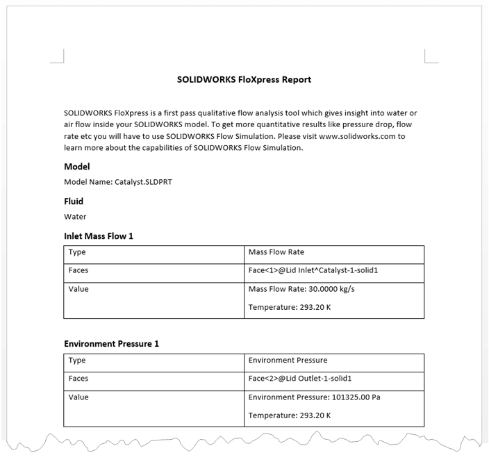
Step 5 – Generating a report:
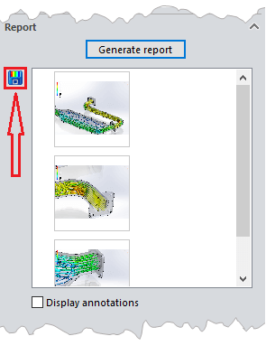
When happy with the results, you can then generate a report using Microsoft Word. This details the parameters and results of the study along with the images as chosen by the user via the “Snap image” button as shown in image 11.
SOLIDWORKS FloXpress is a great tool in terms of gaining an overall idea of how the fluid will behave within the internal cavity of your model and will help to eliminate or reduce the prototype process of your design.
n.b. all simulation results are approximate and need to be verified by real life results. The full package of Flow Simulation provides significantly more detail, flexibility and therefore accuracy.
We hope you found that useful!
Have you seen our blog archive where we have posted plenty of helpful articles? We also have a fantastic video library filled with easy-to-follow videos on a number of topics inspired by other SOLIDWORKS users – take a look. Also, don’t forget to follow Innova Systems on twitter for daily bite size SOLIDWORKS tips, tricks and videos.


