

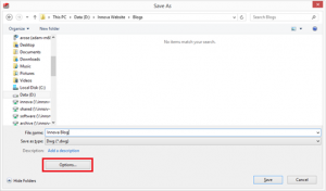
If you are looking to export a SOLIDWORKS drawing to DXF/DWG, it’s not necessarily just a case of saving as DXF/DWG. There are more considerations to be taken such as version, scale and layers. There are various things that can be controlled when going to Options within the save as dialogue.
For this blog we will look at using the mapping options. Using a map file will allow us to automatically generate layers within the DXF/DWG. It will also allow us to specify which SOLIDWORKS entities map to which layer.
Here’s how it works:
When saving your DXF/DWG go into the options and check the box to enable Custom Map SOLIDWORKS to DXF/DWG.
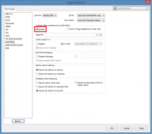
Press OK and save the file. As the file saves it brings up the mapping dialogue box.
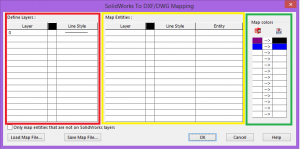
In the ‘Define Layers’ (red) table we can define the default layers that are exported to the DXF/DWG file we can also control the default line style and colour for that layer.
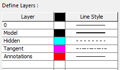
In the above image we have specified a total of 5 layers, with different line styles and colours for those layers. Example; the ‘tangent’ layer will have a default colour of Magenta and chain-dot style line.
In the ‘Map Entities’ (Yellow) table we can control what layer a specific type of SOLIDWORKS entity maps to.
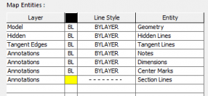
In the above example, geometry (model edges) will map to the model layer using the default colour and line style of that layer.
We have several different types of SOLIDWORKS entities mapping to the ‘annotations’ layer. Notes, Dimensions & center marks will all map to the ‘annotations’ layer using the default line style and colour for that layer. Section Lines will map to the ‘annotations’ but will use a ‘dashed’ line style (instead of the default solid line style) and colour yellow (instead of the default colour red).
In the ‘Map Colours (green) table, we can select the colours applied to SOLIDWORKS entites in the left hand column and map them to the same or a different colour within the DXF.

Once you have filled out the table as you want it, you can save it and use it the next time you want to export a DXF/DWG.
Once you are happy with all your map settings, simply press ‘OK’ and the DXF/DWG will be created. Here’s how it looks:
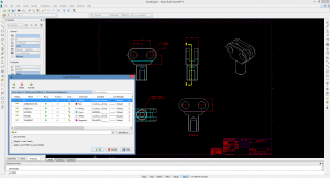
You can see that all the layers have been created as per the map file settings and all the entities have been set to the correct layers.
Being able to map SOLIDWORKS entities to different layers is useful if you need to communicate your work with contractors or clients still using 2D programs.
We hope you found that useful!
Have you seen our blog archive where we have posted plenty of helpful articles? We also have a fantastic video library filled with easy-to-follow videos on a number of topics inspired by other SOLIDWORKS users – take a look.
Also, don’t forget to follow us on twitter for daily bite size SOLIDWORKS tips, tricks and videos.


