
The vent tool is a powerful (but rarely used) feature found on the sheet metal toolbar in SOLIDWORKS. You are not limited to using it on sheet metal parts exclusively, but let’s take a look at how to use the vent tool using this scenario.
The first thing we will need to do is create a suitable 2D sketch. The sketch should represent the shape of your vent including any ribs and spars.
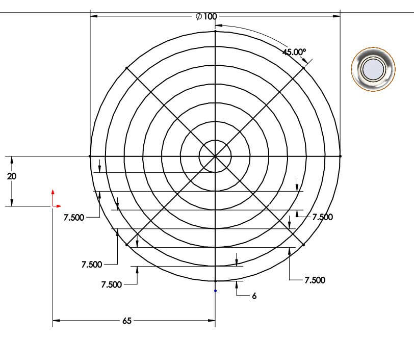
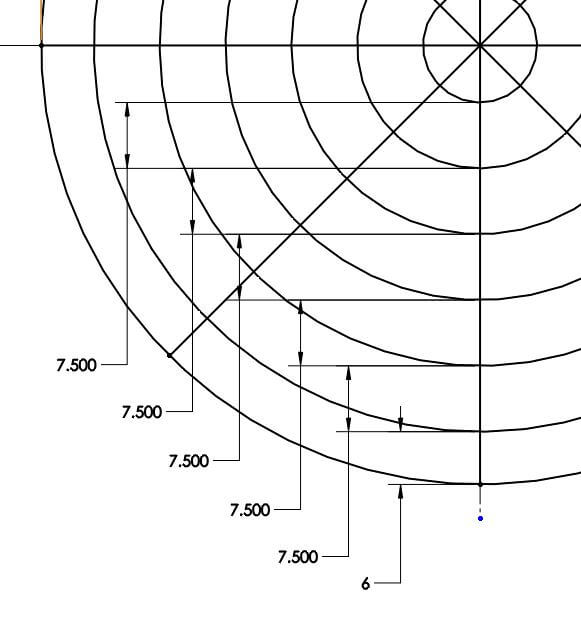
In the above sketch, the outer circle will be the outer boundary of our vent. We have 4 lines intersecting through the circle at increments of 45˚- creating 8 spokes. We also have a number of offset concentric circles, which will form the spars of our vent. Please note the 1st offset circle has a different offset value (6mm) compare to the others (7.5mm) – we’ll take look at the relevance of this later.
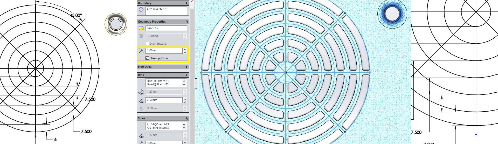
The next step is to launch the vent tool located on the sheet metal toolbar. This launches the property manager, which is where we need to input the required information.
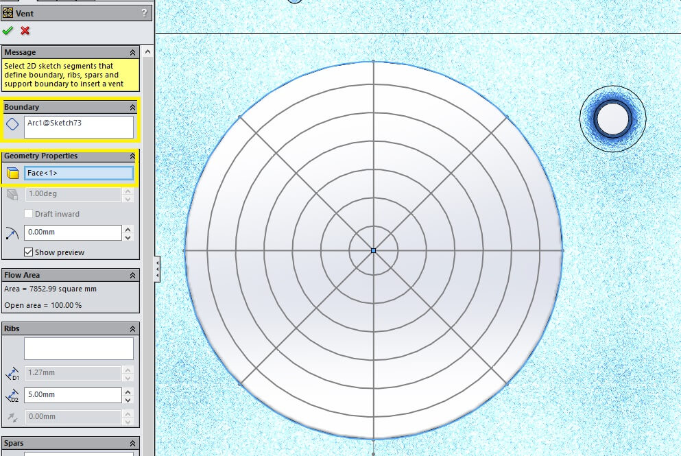
We need to define the boundary and face that the vent is placed on from within the tool. At this stage we will see a circular hole in our part.
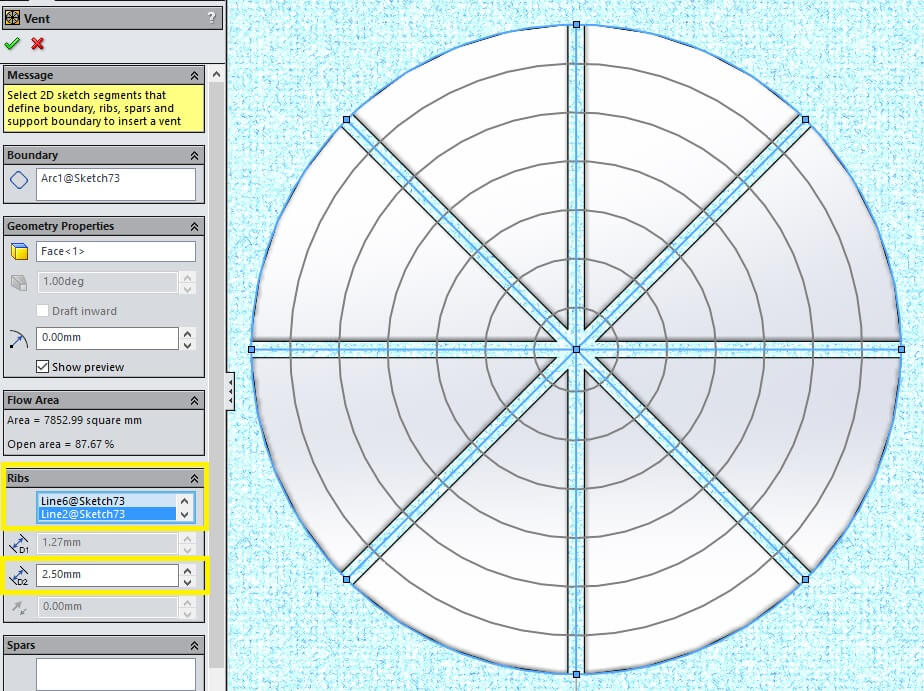
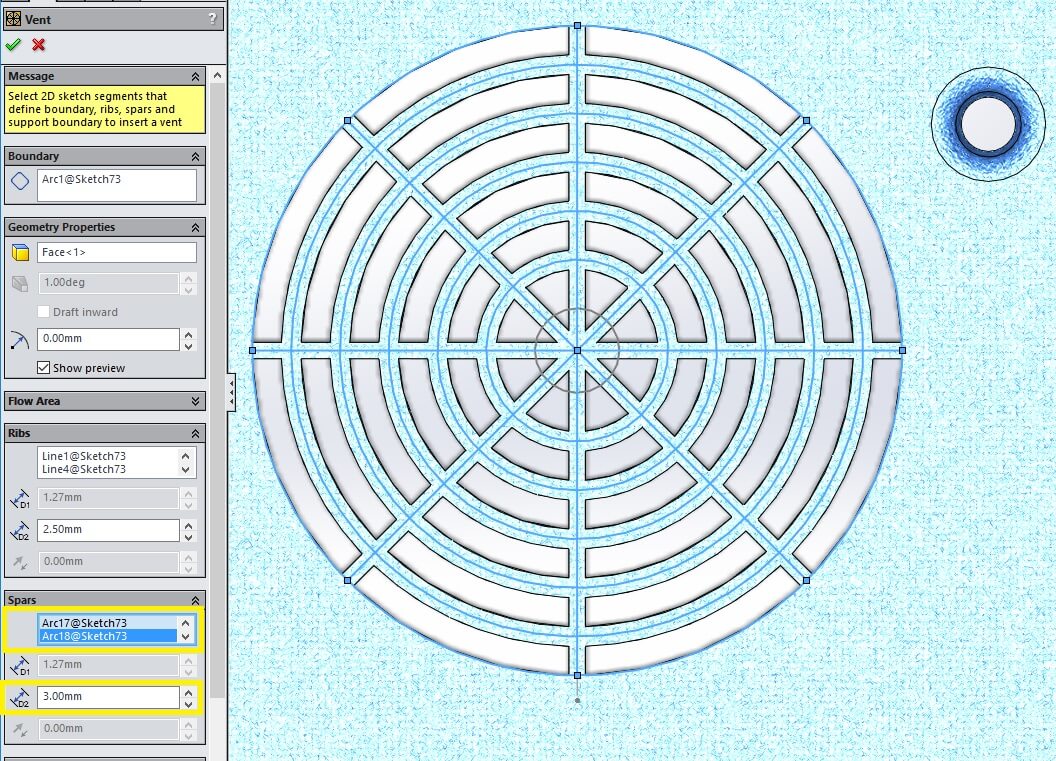
Next, we need to define the ribs. We select the straight lines in the sketch and define the width of the ribs in the property manager.
It is possible to also select the concentric circles, however we would like them to be a different widths, therefore we need to apply them as spars.
We then select all the remaining concentric circles as spars apart from the innermost.
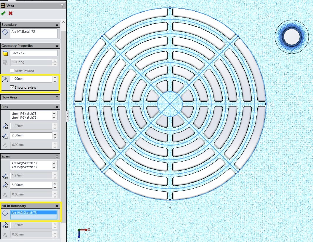
The reason we did not select the inner circle is because we would like to fill in that region with material. To do this we move to the ‘fill in boundary’ section within the property manager and select the inner circle. I can also add fillets to all sharp edges by returning to the ‘geometry properties’ area and defining a value for the fillet.
All that’s left to do now is click the green tick to complete the feature.
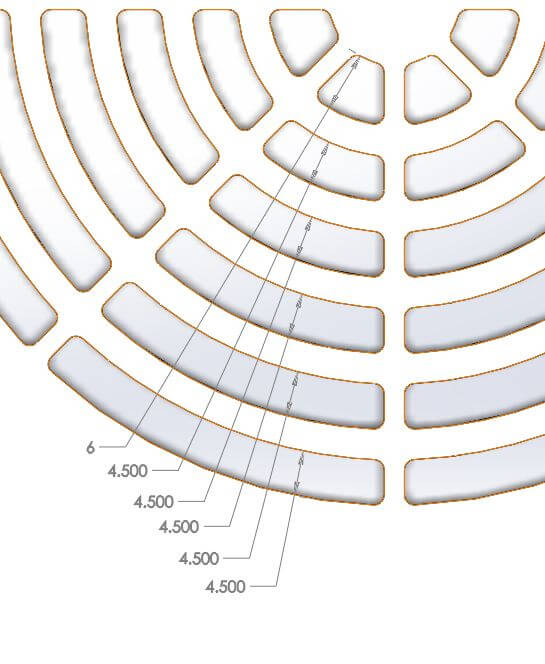
From the images below, you can see that the apertures created at the outer boundary are the same width as all the others apart from the innermost. This is because we created a different offset value on the outside to allow for width of material being applied to the spars about the middle of the sketch line. If we wanted to achieve the same aperture on the inner boundary, we would need to change the offset dimension from 7.5mm to 6mm.
If you take a look at the vent tool property manager in the above images, you will notice some of the commands are greyed out. This is because we have been working with a sheet metal part. If you were working with a non-sheet metal part, it would be possible to define draft angles on vent hole faces, we could also define differing thicknesses for our ribs and spars as well as different height offsets.
We hope you found that useful!
Have you seen our blog archive where we have posted plenty of helpful articles? We also have a fantastic video library filled with easy-to-follow videos on a number of topics inspired by other SOLIDWORKS users – take a look.
Also, don’t forget to follow us on twitter for daily bite size SOLIDWORKS tips, tricks and videos.


