
The Bounding Box fits a virtual cuboid over each unique (non-structural member) solid body and returns the thickness, width and length values and collates them into a description that you can display in your cut list. These values update automatically as the model changes which is ideal for plates with steel structures and panels with wooden structures, such as furniture.
But what if you decide to create your ‘structure’ as an assembly made up of individual components rather than a multibody weldment part? Well, in previous versions of SOLIDWORKS (pre-2018) you’d lose the Bounding Box functionality entirely. This issue was remedied with a new Bounding Box feature in SOLIDWORKS 2018 that’s available for parts and performs an extremely similar operation. However, rather than cut list properties, it populates configuration-specific file properties with length, thickness, width and volume values.
The values that it derives are useful for various applications, such as generating a description for the part to be referenced in your title block or Bill Of Materials (BOM). It also allows you to calculate working stock sizes or do shipping calculations etc.
How does The Bounding Box tool work?
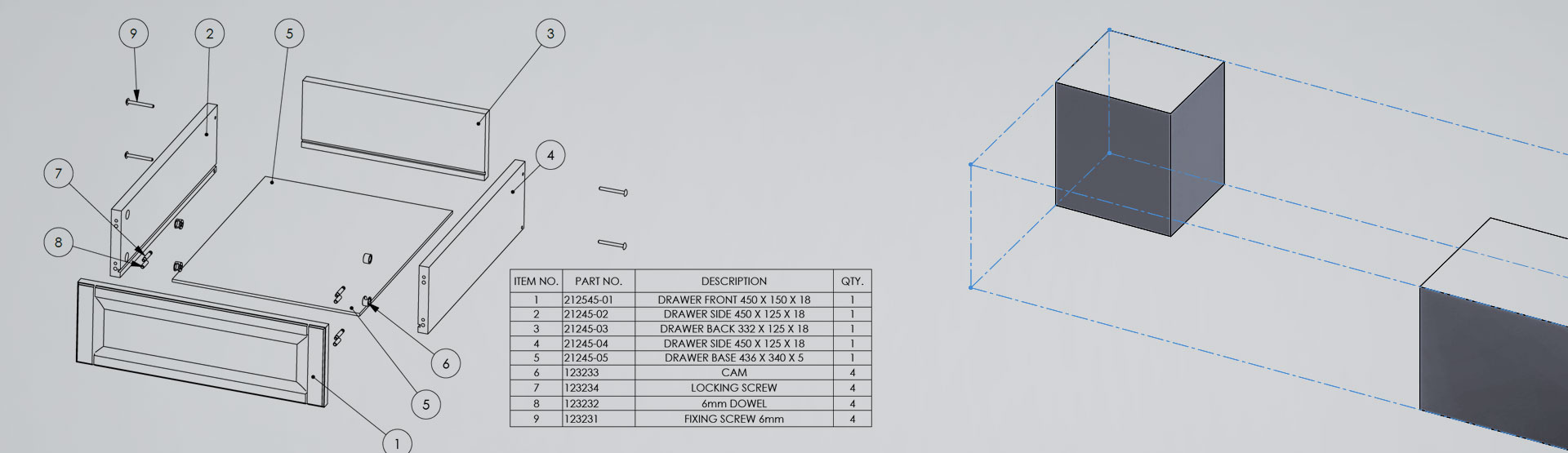
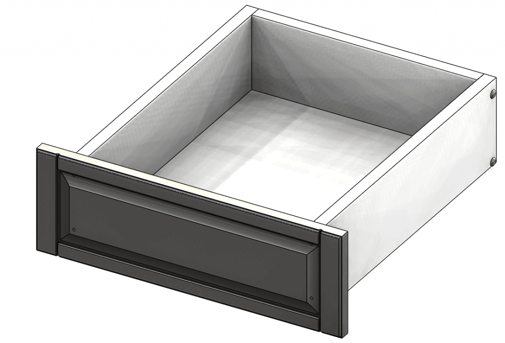
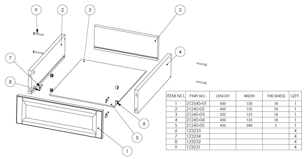
Take a look at the the following example. Here we’ve created a drawer pack assembly where each panel/component is a part.
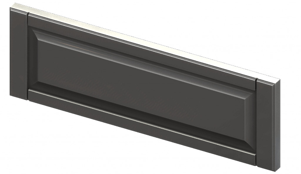
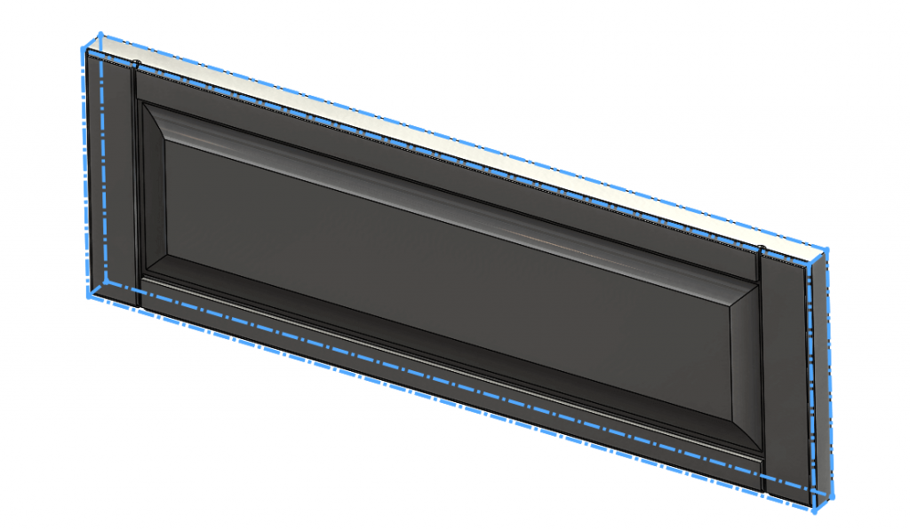
Let’s look at how to apply the Bounding Box feature to the drawer front.
First, launch the tool Reference Geometry -> Bounding Box.
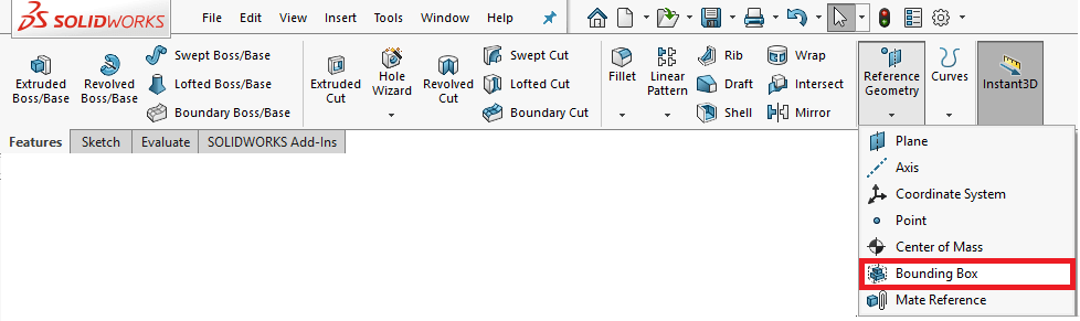
This launches the Bounding Box property manager.
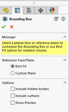
Next, choose the option for ‘Best Fit’ and select the green tick to complete the feature. ‘Best fit’ will fit the smallest possible virtual cuboid around the model geometry. Whereas Custom plane will allow you to choose a plane or planar face to define the Bounding Box orientation.
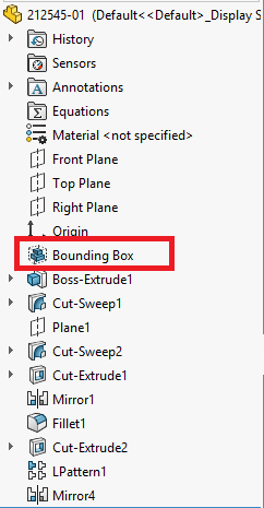
A Bounding Box feature is added to the top of the tree and a virtual cuboid is applied to the extents of the model generated (shown with blue chain dot line).
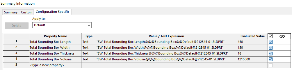
If we now examine configuration-specific properties, you’ll see it generates a total Bounding Box length, width, thickness and volume properties.
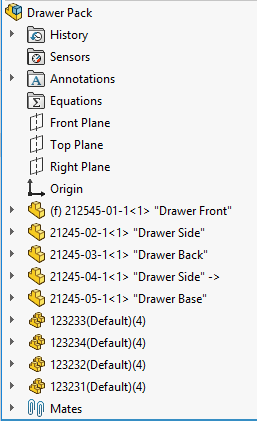
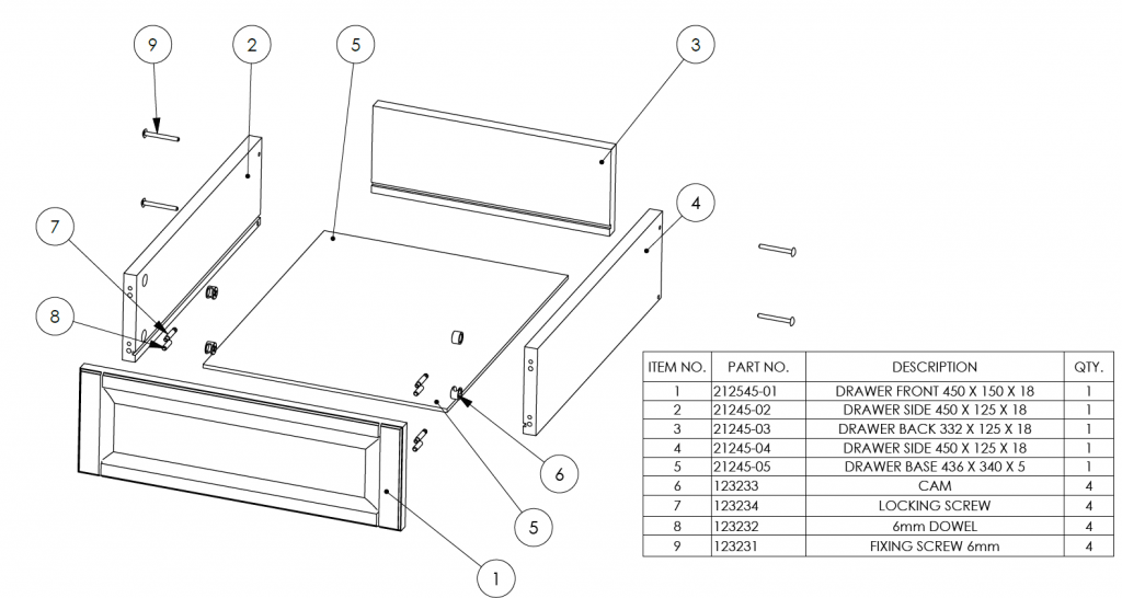
This has been done with all the panels in the drawer pack assembly. If we create a BOM for this assembly, you can see we can reference the Bounding Box values in their own columns.
We can also collate those values into a property called ‘Description’.
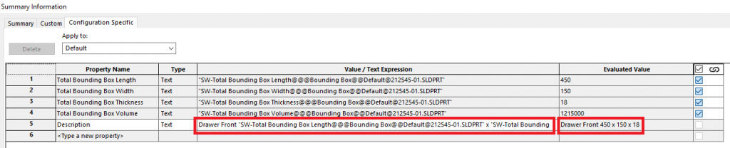
This gives us a parametrically linked ‘Description’ property & the length, width, thickness columns are no longer needed in the BOM.
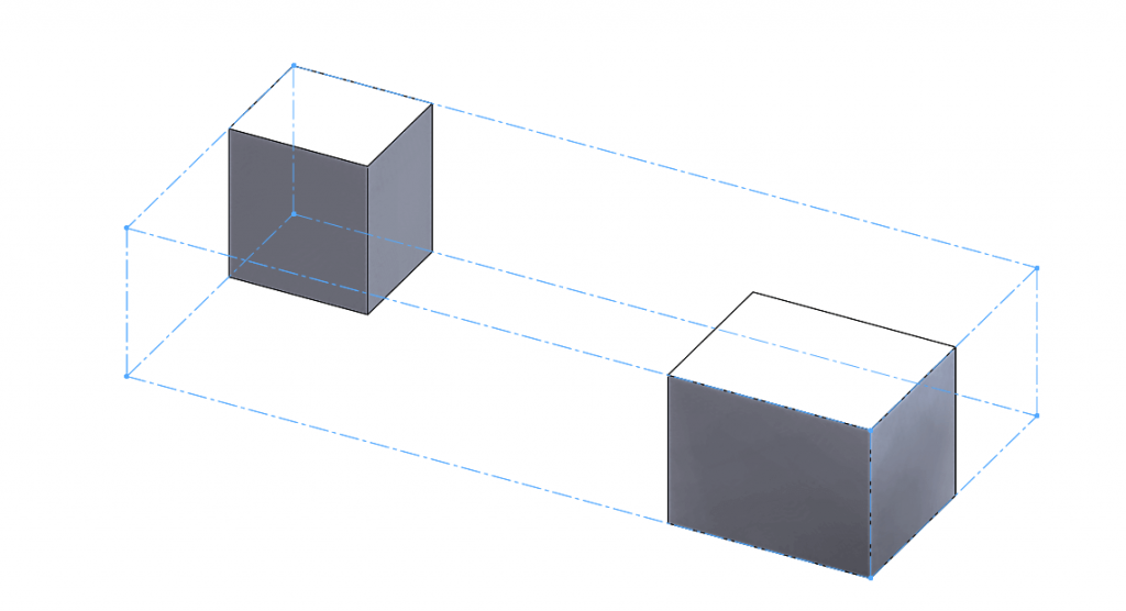
If you do decide to use the Bounding Box feature with a multi body part, it will apply the Bounding Box to both bodies as per the image below.
Additional options within the Bounding Box allow you include hidden bodies, surfaces and show preview.
A welcome update first introduced in SOLIDWORKS 2018!
We hope you found that useful!
Have you seen our blog archive where we have posted plenty of helpful articles? We also have a fantastic video library filled with easy-to-follow videos on a number of topics inspired by other SOLIDWORKS users – take a look. Also, don’t forget to follow Innova Systems on Twitter for daily bite size SOLIDWORKS tips, tricks and videos.


