
[Video transcript]
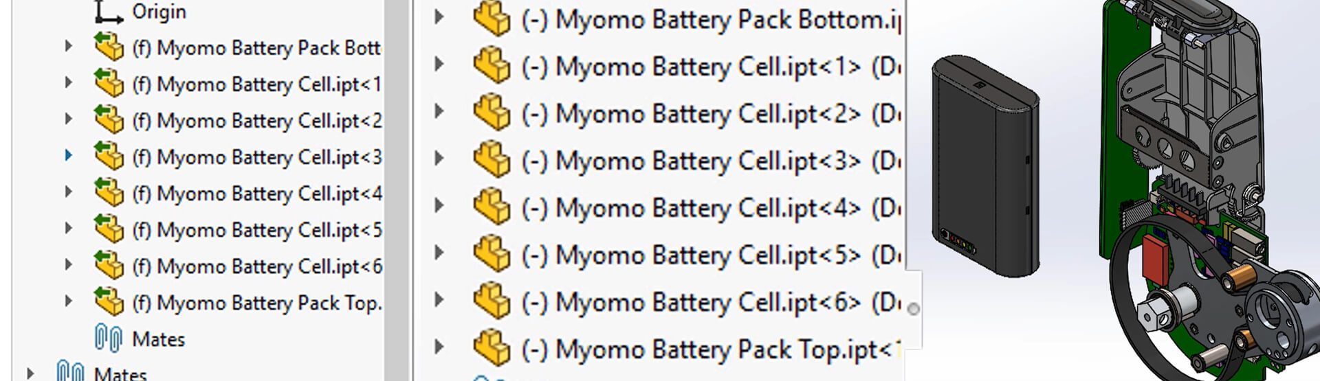
We’ve had a number of customers asking what the green arrows on their SOLIDWORKS part and assembly icons in the tree are. The answer is a piece of functionality called 3D Interconnect, which was introduced in SOLIDWORKS 2017. Prior to this, if we were to work on a third party file, such as Autodesk Inventor, Solid Edge, PTC CREO, and so on, we would need to open the file directly into SOLIDWORKS, at which point it would convert the document to a native SOLIDWORKS file, with no link back to the original data.
When 3D Interconnect was introduced it allowed us to work on these 3rd party files in their native format with no conversion required. Instead, we could drag these files directly into SOLIDWORKS assemblies and, because we’re using the CAD files in their native format, they’re linked back to the original file and are therefore read-only. So, If changes are required, they must be done in the original program that was used to create them. Any changes made would then automatically propagate into your SOLIDWORKS file.
In later releases of SOLIDWORKS, even more file types were included with 3D Interconnect, including STEP and IGES, and it’s with these files where we mostly see the confusion with our customers.
3D Interconnect is on by default, so let’s say you open a STEP file, it will automatically open it using 3D Interconnect. You’ll know if you’ve opened a file using 3D Interconnect because the part assembly icons in the tree will show with a green arrow next to them. As stated earlier, we can’t modify these files because we’re not converting them to SOLIDWORKS files, but reading the data directly.
If you do want to modify the files you have 2 choices:
1) Re-import the file with 3D Interconnect switched off. To turn off 3D Interconnect go to options->import->general and toggle off ‘Enable 3D Interconnect’. We’ll then open the file and as you can see there are now green arrows on my icons in the tree.
2) Dissolve the 3D Interconnect assembly. Right-click on a 3D Interconnect assembly in the tree and choose to dissolve the assembly. This will break the link back the original CAD data. It will become editable, and you will need to manage the document like a standard SOLIDWORKS file.
The translators for 3D Interconnect are different from the standard translators in SOLIDWORKS. So, if you are having issues opening a 3rd party file type, it’s worth trying it with 3D Interconnect on and off to see which gives you the better result.
For more information about using SOLIDWORKS with your existing CAD data,
please call us on 01223 200690, or send a message below.
We hope you found that useful!
Have you seen our blog archive where we have posted plenty of helpful articles? We also have a fantastic video library filled with easy-to-follow videos on a number of topics inspired by other SOLIDWORKS users – take a look. Also, don’t forget to follow Innova Systems on Twitter for bite-size SOLIDWORKS tips, tricks, and videos.


