
First introduced in SOLIDWORKS 2017, Magnetic Mates is a fantastic tool that can significantly speed up the construction of your SOLIDWORKS assemblies. Magnetic Mates allow you to quickly and easily constrain components to each other in an assembly – making it useful for a number of different applications. In the video below, we’ll take a look at how we can use Magnetic Mates to significantly speed up a kitchen layout design. We’ll also look at the added benefits of using SOLIDWORKS for automatic creation of cut lists, bills of materials, drawings, and photorealistic renders.
Watch the video to see Magnetic Mates in action!
Video: Magnetic Mates for faster SOLIDWORKS Assemblies (Kitchen Example)
Video transcript
After taking some measurements from site, I’ve very quickly created a basic room layout, which has been placed in my assembly. Various styles of cabinet are available to me from my design library, but I’m going to use a Shaker style for this example and I begin by placing a corner cabinet.
Let’s open up the unit and look in more detail at how the cabinet was constructed. It’s a sub assembly consisting of a carcass, doors, a plinth and a worktop. I’ve also added in feet, blum hinges and handles. I’ve also generated the various sizes that our cabinet is manufactured to using the configuration tool.
The old way of doing things
Before we start using Magnetic Mates to position cabinets in our assembly, lets take a look at the old method. We mate the base of the cabinet coincident with the floor, the back of the cabinet coincident with the wall, and the side of the cabinet coincident with the corner cabinet. This requires a total of three mates and the selection of six different faces.
The Magnetic Mates workflow
A little bit of work is required upfront when using Magnetic Mates. We use the asset publisher to construct how our Magnetic Mate will function and it asks us for a ground plane, which is the surface that cabinet sits on. I’ve added a plane in my assembly that represents this location. Next I add two connectors – these will be a reference point where the Magnetic Mates from various components can connect to each other. I’ve placed two sketch points in the bottom external corners of the design, I select the points and a face to define the direction and that’s it!
In the assembly I’ll define where the ground plane is – I’ll select the Floor – I already have a corner cabinet which has a Magnetic Mate defined inside of it. Now time to bring in my standard cabinets. The ground planes of the cabinet and assembly constrain themselves to each other & the connectors automatically snap together. Now it’s just a single click to position my cabinet – much quicker & easier than the old method. I’ll bring several more instances, which looks good, but I would like the cabinets to be of different sizes., to do this I simply change the configuration.
Finishing off my kitchen layout
To complete my kitchen layout, I’ll very quickly add end panels, a tall unit, a washing machine and an oven. You can often download CAD models of white goods from manufacturer websites or from the likes of 3D Content Central and GrabCad. Before I move on to my wall units, I’ll just adjust one of my cabinets such that the oven sits centrally between the windows. You can see everything updates really nicely.
For my wall units I create a second ground plane at the height my wall cabinets will sit at. I ensure the ground plane is active. My wall cabinets automatically snap to this plane and to each other. Again, we’ll just modify the configurations of the cabinets we wish to use.
Were almost done, but there’s a problem; We have a cabinet interfering with a boxed beam in our kitchen. Rather than modifying the cabinet on site, we’re going to manufacture the cabinet to include the cut out. Modifying the cabinet at assembly level allows me to constrain the cut-out to the boxed section. And were done.
Were now at the stage where we would like to try and win the business. Our client requires a price, a breakdown of whats included and visuals of how the kitchen will look. Generating a 2d Drawing is easy Our views are automatically generated we just need to place them on our sheet. The Bill of Materials (BOM) is automatic I’ve added a price per unit as a custom property to the components in the assembly – This allows us to show the cost of each item. We can then very quickly calculate a final cost using simple equations inside our BOM. Its also worth noting that we can calculate the quantity of our plinth and worktop based on length, rather than the amount of instances within the kitchen assembly – so we know the meterage required.
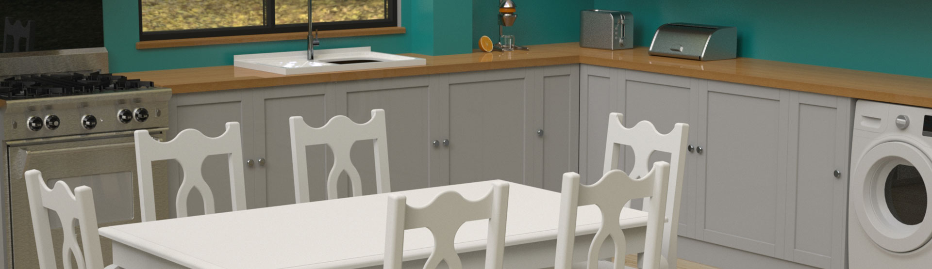
We can use SOLIDWORKS Visualize to create stunning visuals to send to our client with very little additional effort. We simply import our model and paint it. It’s easy to experiment with different colours and finishes. Of course, we could spend more time refining the render by adding lights and custom materials, however I’m more than happy with these results and I’m ready to send the proposal to our client.
Once we’ve won the job, its time to produce our manufacturing data. We’ve used mostly standard cabinets in this job – Therefore we have all the relevant drawings and manufacturing data ready to go. However, there was a special cabinet, where we removed an area for a boxed beam. Lets see how we can generate the manufacturing data for this.
I’ll add additional panels to strengthen where we have removed material and update the cut list to include these panels. From here we can create drawings of each unique panel, as well as industry standard exports for machining these cabinets.
So, we’ve created our kitchen layout extremely quickly and easily, complete with manufacturing drawings, accurate cut lists and bills of materials. Not only that we’ve used SOLIDWORKS Visualize to create stunning renders, so you can impress your client and win their business.
If you’re not using SOLIDWORKS already, please contact our sales team for a personal demo.


