
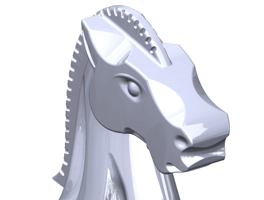
SOLIDWORKS 2018 sees new Mesh Modelling capabilities for working with mesh files (stl, obj, ply, ply2, 3mf). We’re going to take a look at using these Mesh Modelling techniques to design and print a 3D mould tool of a knight chess piece to replace one that was misplaced over the Christmas period. There’s no CAD file available for this part, but we’ve found an STL of a very similar part to what we’re looking for:
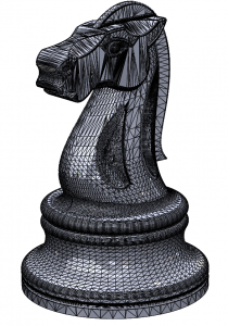
An STL file is made up of lots of facets, as you can see in the above image. The above file is almost exactly what we want, we would like to add a little more definition on the horses mane, however.
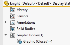
When importing mesh files into SOLIDWORKS, they import as a ‘Graphic Bodies’ by default:
Prior to SOLIDWORKS 2018, there was very little that you could do with Graphic Bodies inside SOLIDWORKS other than view it. New to SOLIDWORKS 2018 are several new tools that allow us to work with these mesh files.
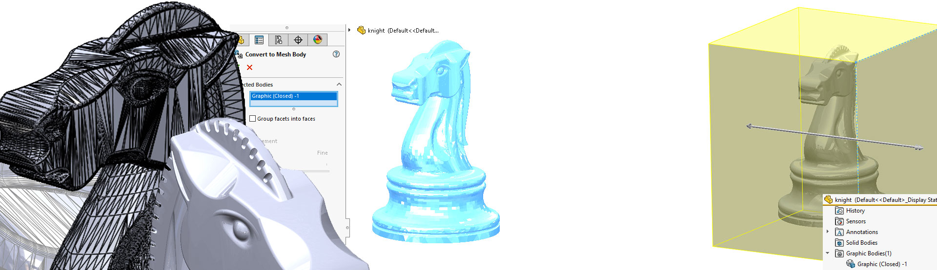
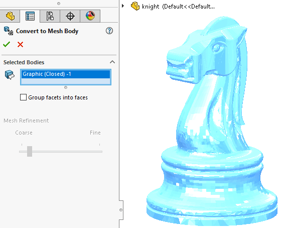
The first thing we’re going to do here is turn the Graphic Body into what is referred to as a ‘Mesh BREP Body’ using the new command ‘Convert Mesh Bodies’:

Simply launch the tool and select the Graphic Body.
If we examine the feature tree, you’ll see that it has added a Mesh BREP Body into the Solid Bodies folder and hidden the original Graphic Body. Note the Mesh BREP Body icon is slightly different to a standard Solid Body:
![]()
A Mesh BREP Body behaves differently to a Solid Body. We’re limited to the following options when working with it:
- Determine its mass properties
- Create reference planes for Mesh BREP Bodies (not Graphic Bodies)
- Select Mesh Vertices when sketching. Create sketch relations to a Mesh Facet Vertex of a Graphic Body or Mesh BREP Body
- Measure distances between mesh elements, using the Measure tool
- Create section views
- Trim surfaces
- Shell, Offset, and Thicken Mesh elements
- Apply appearances and render
- Detect interference
- Perform Boolean operations (combine, intersect, split, move, copy, and cut surfaces)
We mentioned earlier that we were going to modify the mane of the knight. Standard cut operations are not available for us to use with Mesh BREP Bodies, but Boolean operations are. Therefore, we’re going to produce many bodies to subtract from the main.
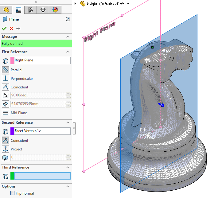
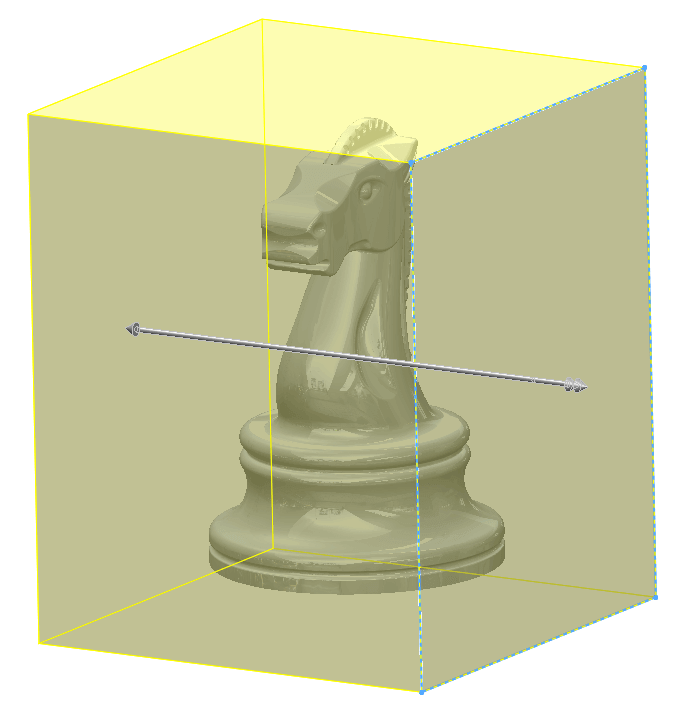
To begin, we create a plane in a suitable location. Let’s offset from the right plane and reference a Vertex from the Mesh on the mane. n.b. referencing the mesh was not possible prior to SOLIDWORKS 2018.
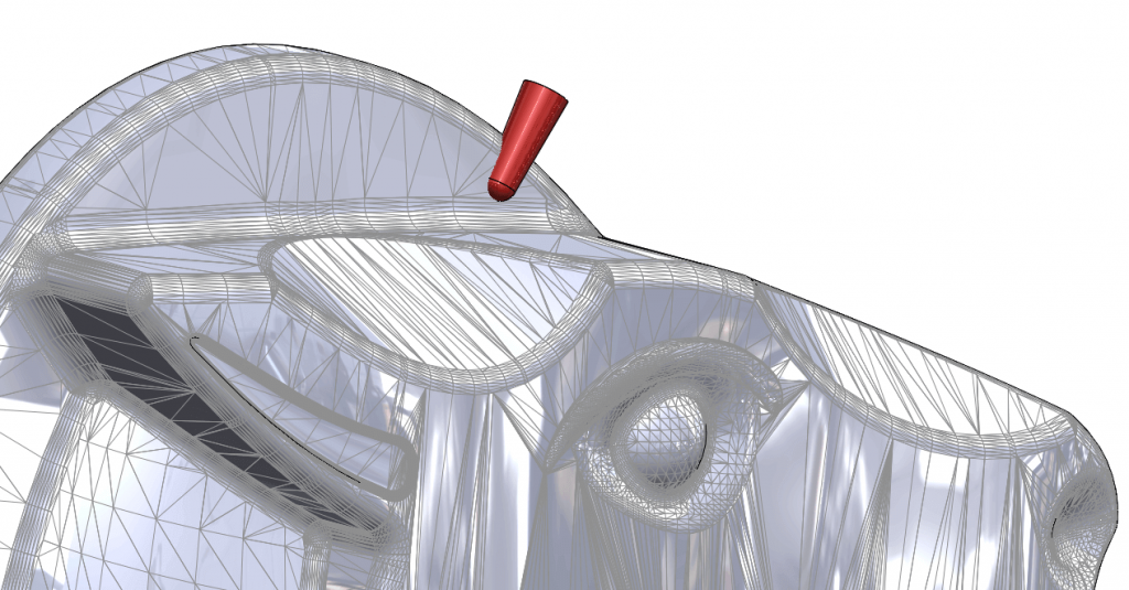
We then create a Solid Body (shown in red) using the ‘Revolve’ command.
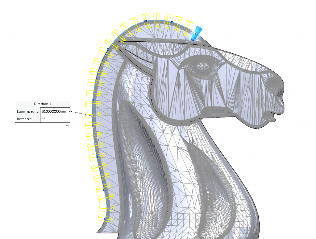
Next (on the same plane) we create a sketch that follows the profile of the knight’s mane. This is then used as the direction curve for a curve driven pattern. The Solid Body is then patterned along the curve.
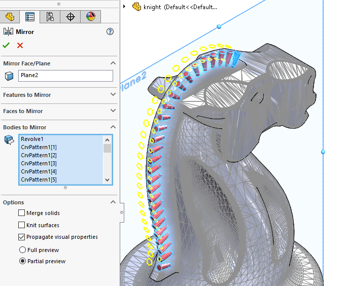
Next, mirror the newly created bodies about the central plane.
Before we can subtract the Solid Bodies away from the Mesh BREP body, they must first be converted to Mesh BREP bodies, making all bodies the same type.
We use the ‘Convert Mesh Bodies’ tool to do this and select all the Solid Bodies from the tree.
Once all Solid Bodies are converted to Mesh BREP Bodies, use the Combine-> Subtract tool to remove all the created bodies from the main knight body. This leaves us with a number of grooves cut into the mane.
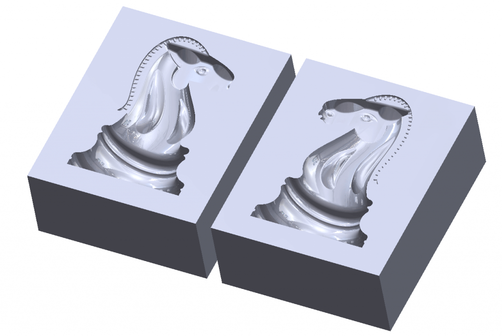
Perfect! Now to create our Mould tool.
First, extrude a cuboid that encompasses the entire knight body:
Next, convert the cube to a Mesh BREP Body using the ‘Convert Mesh Bodies’ tool. We can then subtract the knight body away from the cube, and use the split command to split the body in to core and cavity.
A major stage for creating the tooling for the injection mould is now complete. It’s just a case of adding the gates and the holes for ejector pins etc to complete the design.
With our design complete, it’s time to export it for 3D printing. We can export directly to a 3D print friendly format such as: stl, amf, 3mf using the print 3D options in the file menu.
Job done – We hope you found that useful!
Have you seen our blog archive where we have posted plenty of helpful articles? We also have a fantastic video library filled with easy-to-follow videos on a number of topics inspired by other SOLIDWORKS users – take a look. Also, don’t forget to follow Innova Systems on Twitter for daily bite size SOLIDWORKS tips, tricks and videos.


