
When we create a part in SOLIDWORKS, the position of each body is defined in x,y,z space. When we create an assembly, we use Mates to define components relative to each other. Often, we’re asking SOLIDWORKS to parse a tangled web of various kinds of rules and give us a rational answer. As we might expect, this process is incredibly demanding, so much so that it can become the dominant component of rebuild time. Here, we’ll discuss everything you need to understand to get your SOLIDWORKS Mates working beautifully.
Branches, not loops
The SOLIDWORKS Mate solver is generally flexible and forgiving in the types of scenarios it can handle. Circular sets of references, for example, can be solved iteratively. Ideally though, we want our Mates to be solvable in a logical sequence.
Our first part should be fixed in space, which saves us several Mates at the outset. The next should be defined relative to the first, and subsequent Mates defined relative to the already mated geometry. A good rule-of-thumb is that relations should be in branches, without looping back if at all possible.
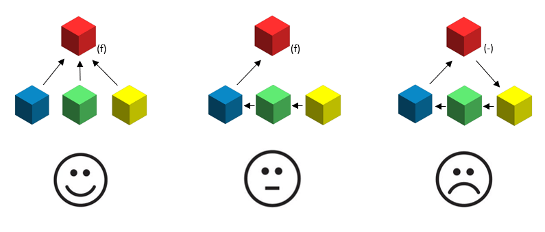
Long chains also increase rebuild time and the likelihood of errors, so try to Mate many parts to one part if you can.
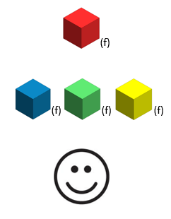
If we want to speed things up further, we can fix non-moving components in space after their positions are determined, suppressing the Mates which we used to initially place them. It might be worth creating a separate configuration set up like this:
Make a pyramid using Treehouse
A good hierarchy of sub-assemblies is absolutely crucial.
SOLIDWORKS solves the sets of Mates in each sub assembly independently, solving the top level only on rebuild. If we keep roughly the same, low-ish, number of Mates at each level, we can minimise the solve time. For example, imagine there are 36 Mates needed in total. 6 Top level Mates, plus 5 sub-assemblies of 6 Mates, is vastly better than 36 Mates all at the top level. Now you’re a 6×6 systems of equations instead of a 36 x 36 system of equations.
SOLIDWORKS Treehouse is a great way to visualise your assembles, which should have a nice pyramid type shape to them, not a blob shape (too many parts in one assembly).
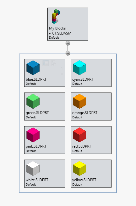
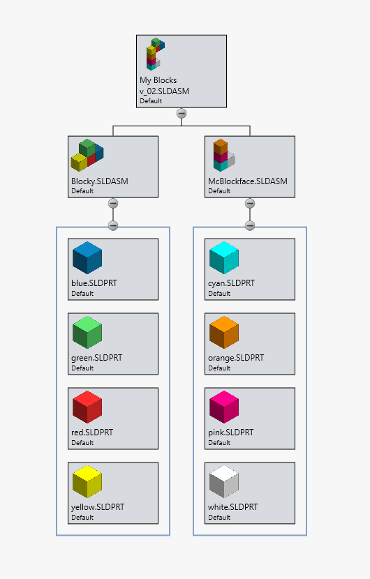
Our pyramid should be structured according to our design intent regarding what needs to be able to move at each level. If we’re building a car, the differential gears or door hinges might be mated at the top level, but the cushions will be mated in the ‘seat’ sub-assembly.
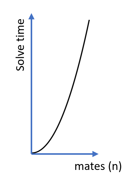
How much does a SOLIDWORKS Mate cost?
Roughly speaking, the time taken to solve a system of Mates is proportional to n2, where n is the number of Mates. This is not bad – when we consider that solution time for a matrix, for example, usually scales n3. However, it’s worth appreciating that adding more Mates becomes progressively more expensive as our assembly grows.
The most restrictive Mates are best. It’s preferable, for example, to use faces rather than edges and vertices. We should generally avoid mating to reference geometry and assembly level features.
Limit angle and distance Mates are the slowest to calculate and should be avoided whereever possible. It’s also worth considering that Mate types such as profile centre and hinge may allow us to replace multiple Mates with one.
Degrees of freedom
We want to keep the number of degrees of freedom for movement in our assembly to a minimum. With floating, unmated parts, we have six Degrees Of Freedom (DOF) per part. In a fully defined assembly, we have zero. More DOFs slow things down a huge amount, especially if they’re spatially interrelated. Locking the rotation of concentric Mates (in the Mate property manager) is one way to reduce the final number of DOFs.
SOLIDWORKS likes to let us play with things by dragging them about. For Mates, this will allow us to understand the DOFs of the model. SOLIDWORKS will also take in to account the initial positions of components when finding a solution. Starting them off in the correct orientation and approximate location prior to mating is always a good idea.
Don’t be redundant
In sketches, over-definition is strictly forbidden. In Mates, the solver is kind to us, and will often still find an answer. We can talk about redundancy and true over definition as distinct cases.
Redundancy is more easily created by accident. This happens where the position of a part is defined in more Mates than necessary, but those Mates agree on the position of the part. SOLIDWORKS can usually deal with this scenario, if the Mates aren’t distance and angle. There is, however, a computational cost, and the solution may be hard to fix if conflicts arise in the Mates.
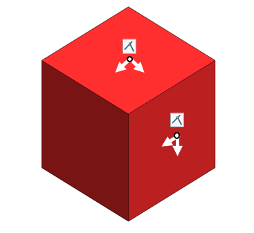
Some redundancy may be unavoidable. For example, a cube with two coincident Mates on perpendicular faces will be over-defined, because each Mate removes a translational degree of freedom in two directions (and a rotational DOF in two directions). The figure below, for example, shows the translational DOFs (white) removed by two coincident Mates.
What should absolutely be avoided is true over definition – conflicting Mates. Conflicting Mates can often be solved in SOLIDWORKS because the software will look for the ‘least bad’ solution. This involves running through all possible solutions and requires even more processing time.
Mating rules for specific features
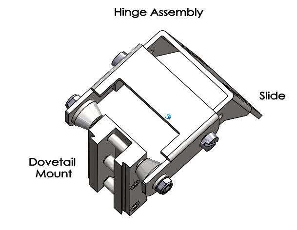
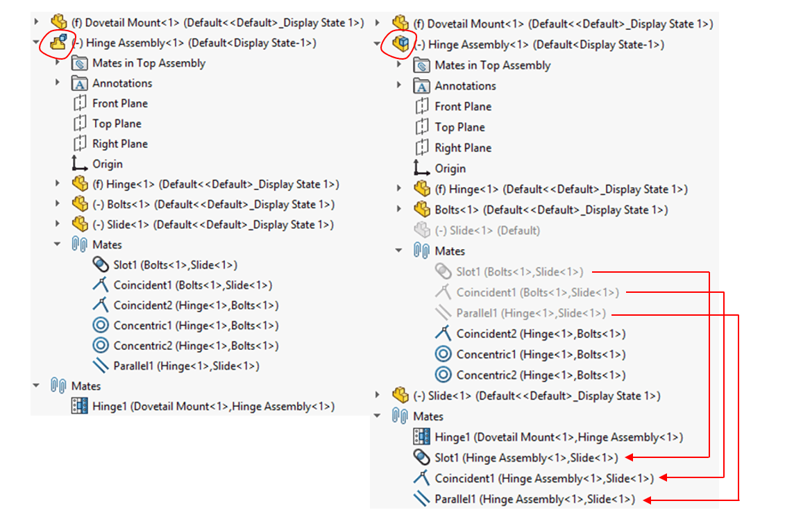
Flexible Sub-assemblies solve all the Mates at the top level. Consider moving only the Mates which are used for motion to the top level instead of making sub-assemblies flexible. Especially be weary of nested flexible sub-assemblies.
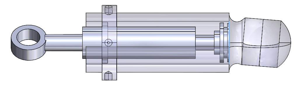
For example, here we have a hinge assembly attached to a dovetail mount. Within the hinge assembly there is a slide which moves via a slot. As we know, when we move the slide and its three Mates to the top level, this will increase our rebuild time. However, this is a preferable way to achieve motion in the slot than making the hinge assembly flexible, which effectively moves all six Mates to the top level, solving irrelevant Mates on rebuild also.
For In-context Relations, Mates should always be added before the relations, preferably with full definition. This ensures that we don’t get a loop where the component geometry updates, requiring the Mates to re-update, requiring the geometry to update, etc, etc.
When using Component Patterns, the positions of the patterned components will be based on the Mate solution. Therefore, it’s good practice to avoid mating to pattered instances, because this will create a complex scenarios with many possibilities to process.
When using Limit Mates in complex assemblies (especially with components at angles), it may be necessary to set the distance / angle so that it is not precisely equal to the limit. This will avoid rounding errors which could cause the components to be outside of the limits. Limit Mates will solve better at the top level rather than in flexible sub-assemblies.
Lightweight and Large Assembly modes will sometimes not solve complex Mates such as tangency and points on curves with the full resolution. Setting to ‘Resolved’ may fix some problems here.
The group solution process
Warning! This bit gets technical
In times gone by, the SOLIDWORKS user had to manually define Mate groups. Creating a good Mate solution was a delicate art. Modern SOLIDWORKS does it all for us, using the following process (from the SOLIDWORKS knowledge base):
– Parse the Mate group to identify the order in which the Mates need to be processed taking account of the interdependencies between the components / sub-assemblies.
– Process the Mate group in the order derived by the parse process.
– Verify the validity of the processed Mates.
– If errors are found, process the Mates again in the order derived from the parse operation.
– Verify a good result and if not raise warnings / errors.
For user purposes, the takeaway here is that for the most complex models, keeping the interdependency of Mates clean, so that there are distinct groups which can be solved together will be a big help to the software.
Tools > Evaluate > MateXpert can be used to see subsets of Mates which are conflicting with each other.
We hope that this deeper dive into the SOLIDWORKS Mate solver will usefully inform your modelling technique. The level of abstraction of the SOLIDWORKS Mate solver, whilst impressive, can sometimes allow us to create complexity without thinking about it. Mindfulness of what you’re telling the program to do, and maintaining simplicity wherever possible, will keep your largest assemblies stable and efficient.
We hope you found that useful!
Have you seen our blog archive where we have posted plenty of helpful articles? We also have a fantastic video library filled with easy-to-follow videos on a number of topics inspired by other SOLIDWORKS users – take a look. Also, don’t forget to follow Innova Systems on twitter for daily bite size SOLIDWORKS tips, tricks and videos.


