
One of our favourite new areas of functionality in SOLIDWORKS Simulation Professional 2018 is Topology Optimisation, a fantastic tool that utilises SOLIDWORKS Simulation’s intelligence to edit the geometry of a part, based on specified simulation parameters. Previously, a trial and error technique was required in order to determine the optimum geometry to withstand the applied loads. This usually resulted in significantly more time and therefore money to achieve the desired geometry. Due to this, over-engineering has been common practice because time is always precious within the engineering sector.
The Topology Optimisation process is relatively straightforward, and certain user-defined parameters can be used for additional control.
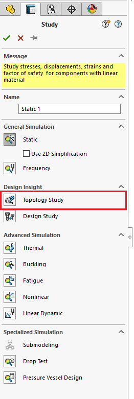
Shown in Image 3 above, the PropertyManager includes a new study type named “Topology Study”, under “Design Insight”.
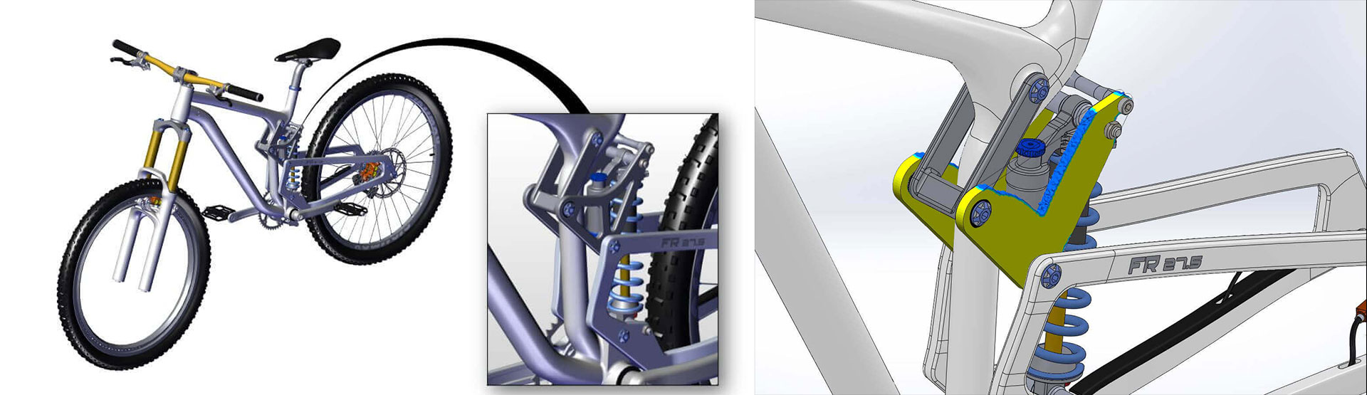
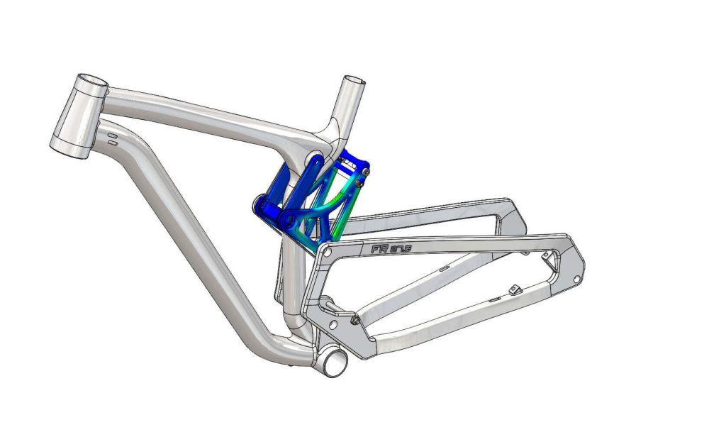
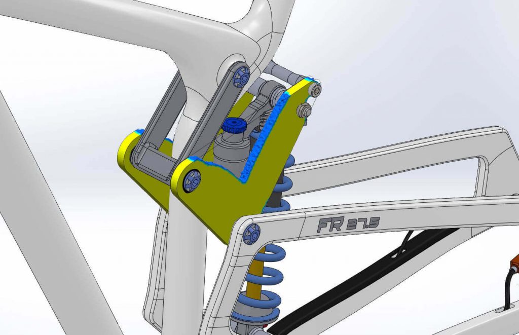
In this example, a study has been carried out for the rear suspension bracket on the bicycle. As you can see it is possible to start with just a basic piece of geometry, allowing just a simple idea of the shape to begin with.
When setting up the study, the parameters available to you are edited either within “Goals and Constraints” and/or “Manufacturing Controls” within the Simulation study tree.
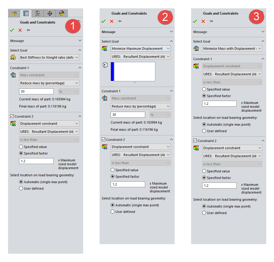
Goals and Constraints
Here you can choose one of three things (see image 6). This choice is integral to the end result of the study.
Best Stiffness to Weight ratio: This option allows you the find the stiffest structure possible given the material removal. A percentage or absolute value can be defined, giving the solver a range to work within to achieve the stiffest model possible. A second constraint can also be added for additional control.
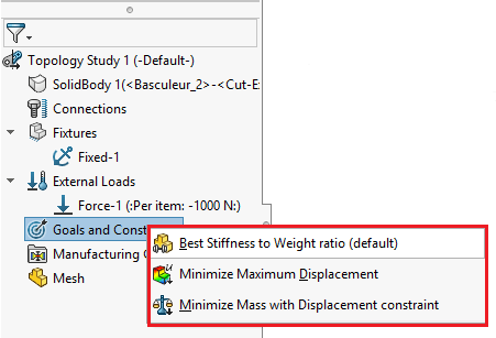
Minimise Maximum Displacement: This option allows you to minimise the displacement at a particular vertex.
Minimise Mass with Displacement constraint: This option allows you to minimise the mass by specifying a maximum overall displacement value at a specific point or the maximum of the model, again an additional constraint can be applied.
Manufacturing Controls
This gives the user an opportunity to add some manufacturing information that would affect the geometry from being edited in a technique that would hinder the manufacturing process.
Add Preserved Region: This gives you an opportunity to prevent specified faces from being removed due to aesthetics, surrounding geometry, etc.
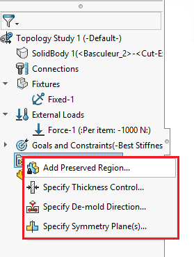
Specify Thickness Control: Allows you to specify the minimum and/or maximum thickness the model can be altered by.
Specify De-mold Direction: This option relates to various methods relating to manufacturing via casting, such as pull direction.
Specify Symmetry Plane(s): Allows the use of symmetry of the optimised shape of the model, either ½, ¼ or ⅛ is available.
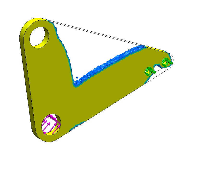
The image below illustrates the geometry SOLIDWORKS has developed as a result of the parameters specified in the study. Notice that SOLIDWORKS has automatically removed any geometry that hasn’t experienced adequate stresses.
Once the study has completed you view the model in a “Material Mass Plot”. The quality of the plot is a direct result of the mesh density. You then have the option to take the altered model and export it via the command “Export Smoothed Mesh” as shown below. This can then be inserted into the active or a new configuration, and even into a new part. In addition to this there are advanced options to export as a graphics, surface and solid body.
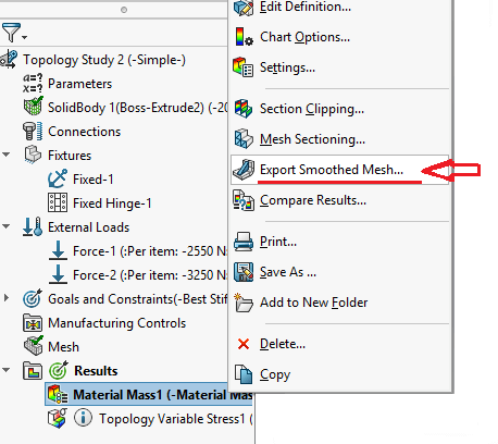
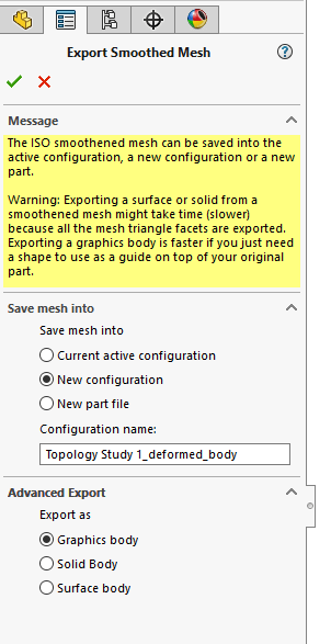
Exporting as a graphics body is a great technique for 3D printing as you can directly export as a .stl file and the export process is a fantastic way of visualising your model in-situ to see if it is acceptable or not.
The new geometry can always be used as guidance and further modifications can then be made, achieving the end result much quicker than the old trial and error technique!
We hope you found that useful!
Have you seen our blog archive where we have posted plenty of helpful articles? We also have a fantastic video library filled with easy-to-follow videos on a number of topics inspired by other SOLIDWORKS users – take a look. Also, don’t forget to follow Innova Systems on Twitter for daily bite size SOLIDWORKS tips, tricks and videos.


