
This tutorial focuses on how to use a Bump Map in SOLIDWORKS Visualize to add a customised “textured” look to your renders. It’s the first of five tutorials based on the content of this video where our Technical Manager, Ed Hawkins, recreated a classic Tiger Woods shot from The Masters Golf Tournament.
The techniques covered are as follows:
- Using bump maps in appearances (this tutorial)
- Mapping and scaling textures in SOLIDWORKS Visualize
- Using displacement maps in Visualize
- Using backplates when rendering in SOLIDWORKS Visualize
- Modifying your SOLIDWORKS models to add realism to your renders
So without further ado…
Why use a Bump Map?
A Bump Map is a great way to quickly improve the realism of an appearance in SOLIDWORKS. This is because it makes your model look more geometrically complex, without the effort of having to model in the complexity manually.
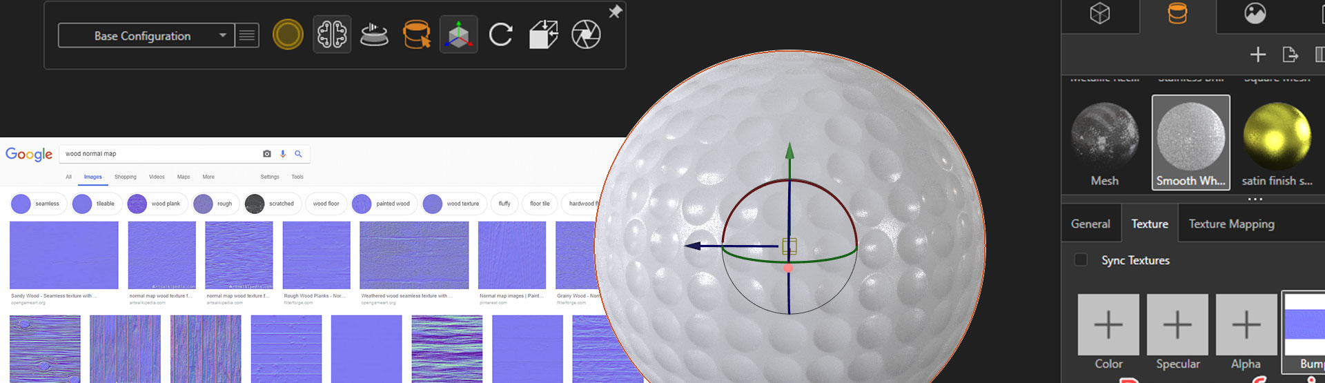
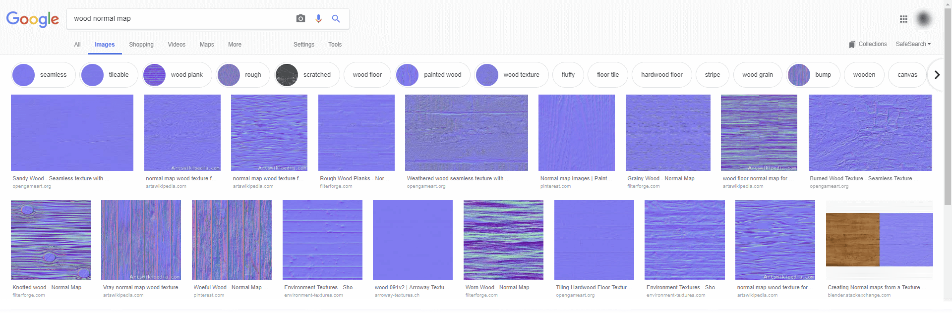
Before going through and creating a new appearance, a bump map will be sourced, either from within Visualize, or from an image library on your computer, or even the Web. Simply Google searching for the name of the appearance you’re looking for followed by “Texture”, “Bump Map” or “Normal Map” will often yield plenty of results. However, make sure that the image you’re using isn’t copywritten before including it in your render!
How to apply your chosen images to your render
Firstly, apply a material which is similar to the one you’re after. This can be done from Visualize’s existing appearance library.
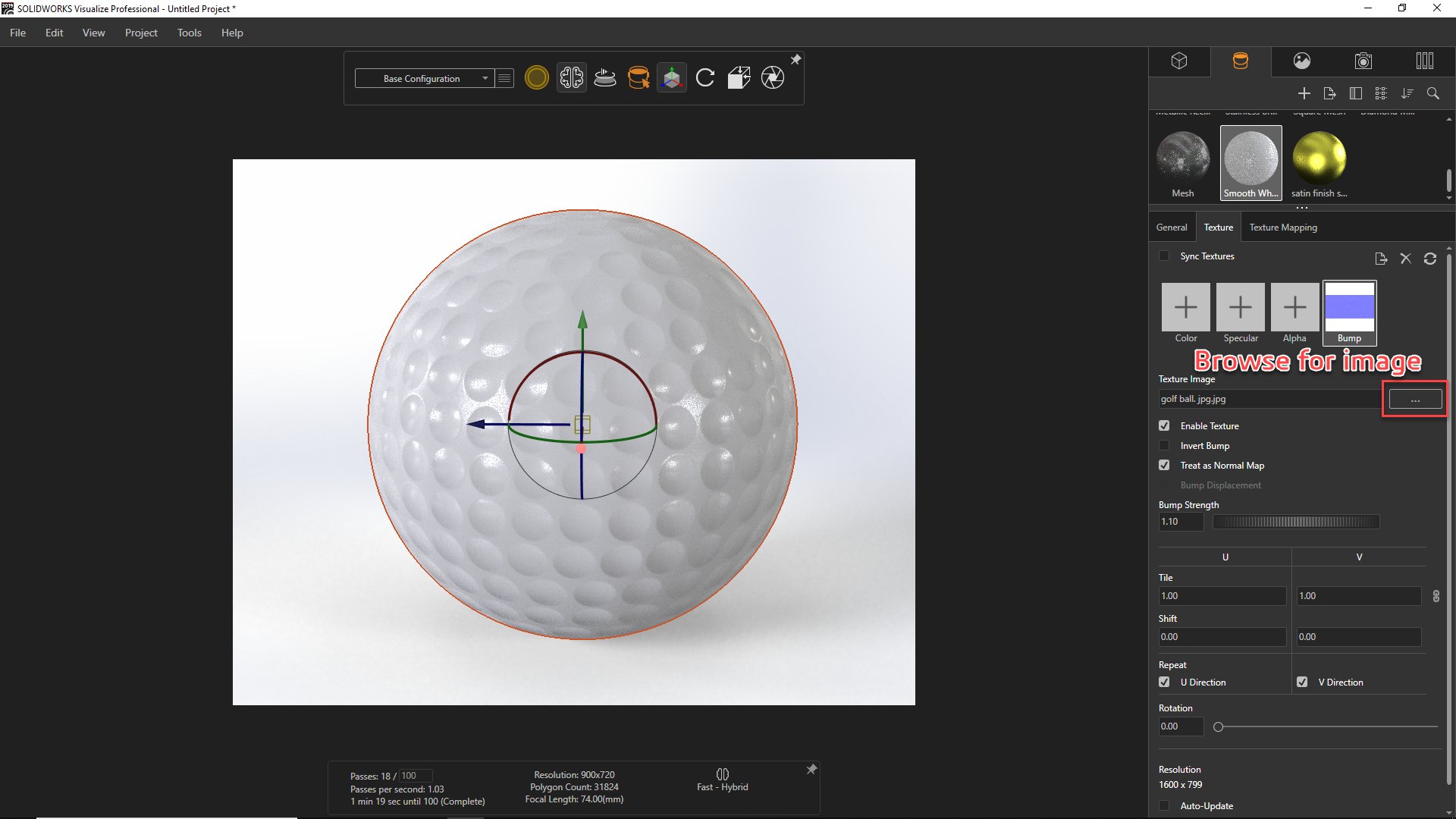
After applying the appearance, the Bump Map can be added from the Texture tab when the appearance is selected. In the example shown above, a Golf ball bump map has been applied to the model using an image. After application, the mapping may need to be corrected on the surface. If this is something you are struggling with, make sure to check out our mapping and scaling textures in SOLIDWORKS Visualize tutorial.
There are a few options which can be modified to get the appearance looking right:
- Enable texture: Use this to turn the Bump Map on and off.
- Invert bump: This inverts the Bump Map, making concave areas convex.
- Treat as normal map: Different images can be used; Bump Maps (greyscale) or Normal Maps (RGB). Use this option to toggle between them.
- Bump Displacement: This will be covered in a separate blog see Using Displacement Maps.
- Bump strength: The most important option, it can be varied to adjust the Bump height. Negative values do the same as inverting the Bump Map.
So there you have it. You should have a must more realistic appearance after adjusting these settings. You can take it even further by combining this map with an Alpha Map to create holes in an appearance, or a Specular Map to add location specific highlights. Give it a try.
We hope you enjoyed this SOLIDWORKS Visualize tutorial.
Have you seen our blog archive where we have posted plenty of other helpful tutorials and news articles? We also have a fantastic video library filled with easy-to-follow videos on a number of topics inspired by other SOLIDWORKS users – take a look. Also, don’t forget to follow Innova Systems on Twitter for daily bite size SOLIDWORKS tips, tricks and videos.


