
The Displacement Map and the Bump Map are produced using very similar methods. If you haven’t heard of Bump Maps, we recommend reading our SOLIDWORKS Visualize Bump Maps tutorial before starting this one, as you will learn how to correctly apply textures to your model in SOLIDWORKS Visualize.
First of all, let’s look at the difference between a bump and displacement map.
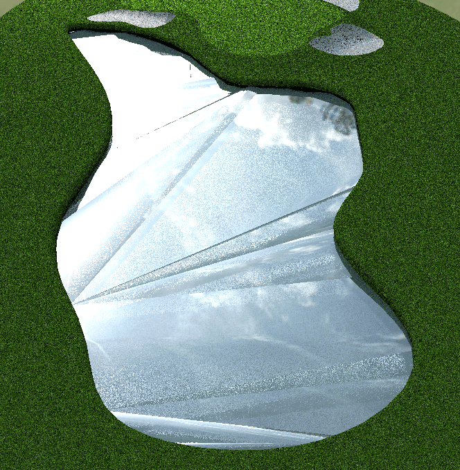
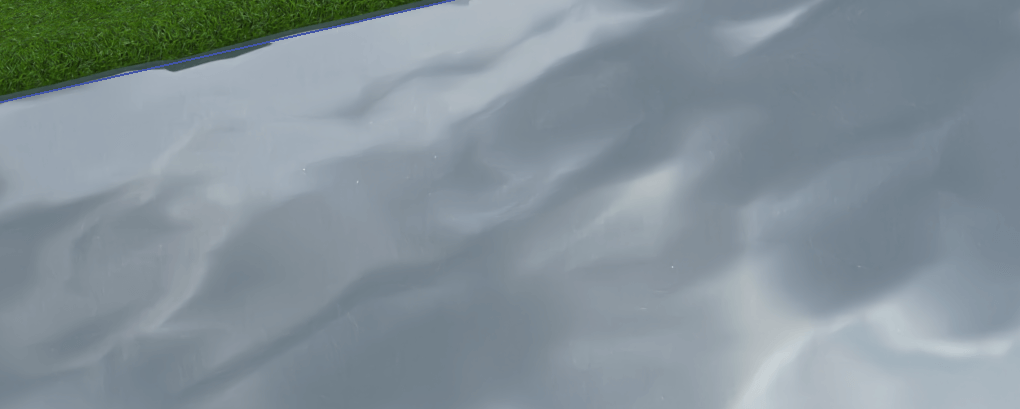
The Displacement Map
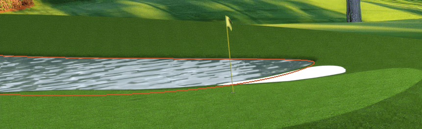
The Bump Map
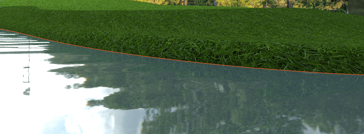
In the examples shown you can see that the displacement map is actually displacing the surface to create the rippled look of this water. The Bump Map keeps the surface flat, affecting only the light scattering directions.
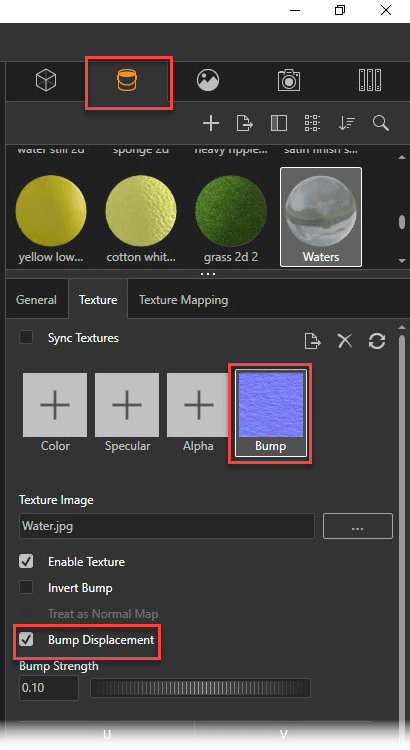
In order to use a displacement map in SOLIDWORKS Visualize, navigate to the Appearances tab and select the appearance you want to test it on. Select the Texture tab > Bump map and if you have a texture loaded you can select the bump displacement option (ensure treat as normal map is unticked).
Please keep in mind that highly detailed displacement maps are quite resource-heavy, so if you’re having trouble, keep an eye on the Windows task Manager to see if you’re maxing out your computer’s RAM or VRAM. Take a look at our currently recommended Desktop and Laptop specifications for more information on hardware.
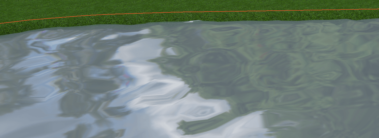
When you turn on the Bump Displacement option, it may look a little funny. You can see in the image below that our render looks more like ice than water. This is because the Displacement option will offset the geometry of the surface using the current tessellation of the surface as it is in SOLIDWORKS.
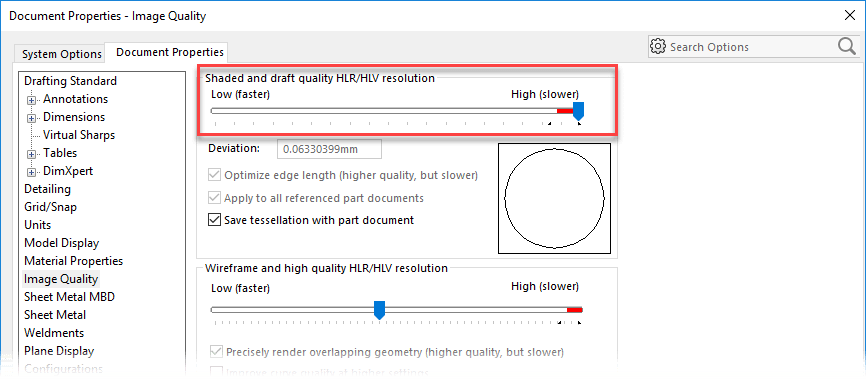
This can be improved by increasing the image quality of the model in SOLIDWORKS Options > Document Properties > Image Quality
You may find this is sufficient for your model. However, in the water example shown above a further step needed to be taken. Thankfully this process is easy in SOLIDWORKS 2018 onwards because of the option to convert a model to a mesh body.
Note – you may want to create a copy the body of your body before taking this step. This can be done using move/copy body. Insert menu > Features > Move/Copy Body – you’ll see a tick box to copy the body.
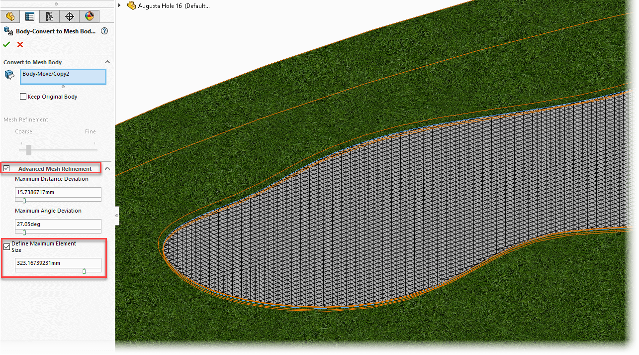
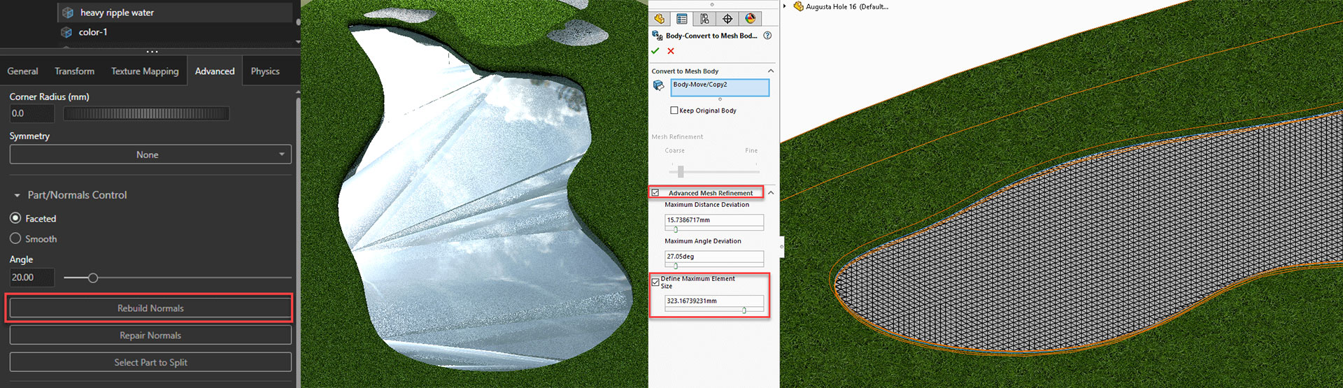
You’ll find the option to convert to mesh body under the insert Menu > Features > Convert to Mesh Body. Alternatively, you can also right click the body from the Solid or Surface bodies folder (if showing). Using the advanced mesh refinement and defining the maximum element size you can give SOLIDWORKS Visualize a fine surface tessellation to work with.
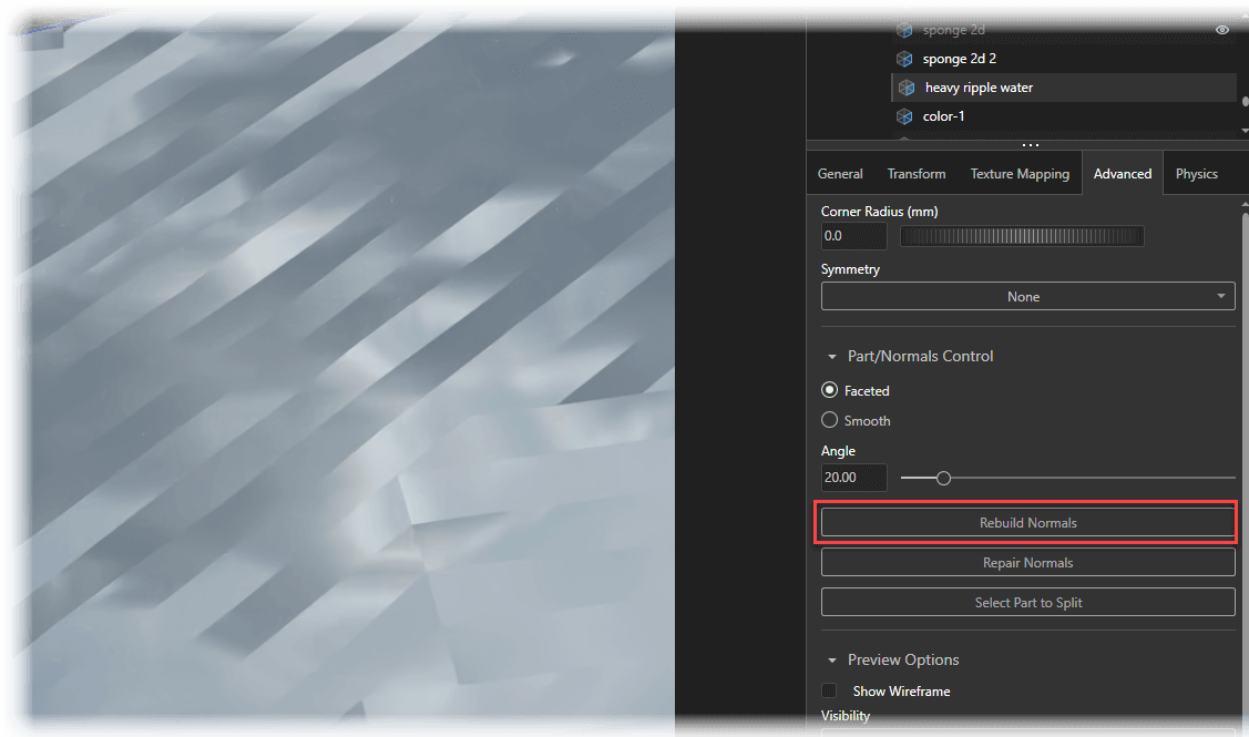
After creating this mesh, go back to SOLIDWORKS Visualize and test the Bump Displacement again. In Visualize if the tessellation on the part is still a little too faceted for your appearance you can improve this by taking the following steps: Select the part in question (part selection mode), on the Advanced tab you will see the Rebuild Normals option. This will rebuild and optimise the entire part mesh. You should find the results are far better!
Before you go…
Check out these related posts:
- Using bump maps in appearances
- Texture Mapping & Scaling in SOLIDWORKS Visualize
- Using backplates when rendering in SOLIDWORKS Visualize
- Modifying your SOLIDWORKS models to add realism to your renders
We hope you enjoyed learning how to use Displacement Maps in SOLIDWORKS Visualize.
Have you seen our blog archive where we have posted plenty of helpful tutorials and news articles? We also have a fantastic video library filled with easy-to-follow videos on a number of topics inspired by other SOLIDWORKS users – take a look. Also, don’t forget to follow Innova Systems on Twitter for daily bite size SOLIDWORKS tips, tricks and videos.


